TWI/I2C no communication with Sensor Devices

Hello,

my first Post here, so i hope i do it correctly.

I have the following Problem with the Configuration and Communication over TWI/I2C.
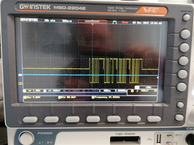
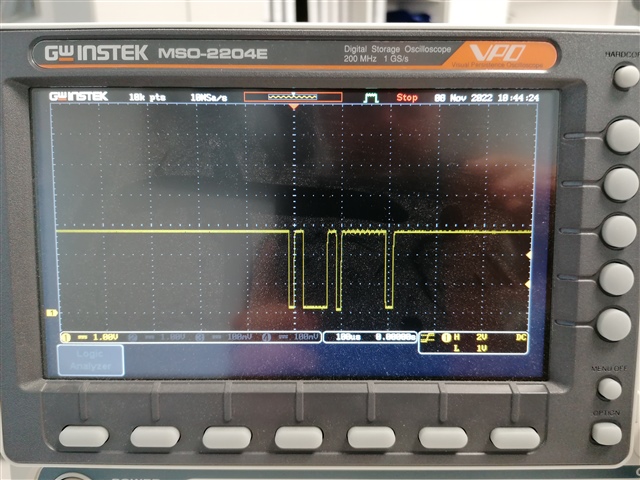
The Voltage of the TWI/I2C Bus is not 3.3V.

Reference Mesurment with a RPI and ESP32 for the same Sensor Hardware. I can say it's not a hardware fault.

I use as Hardwarebase the nRF52833-DK.

As Development runtime Zephyr with the nRF connect SDK V2.0.0 in Visual Studio Code.

As Test-Project to find the Problem, i use the follwing Code and Settings:

The used Overlay for I2C

&i2c0 {
	compatible = "nordic,nrf-twim";
	status = "okay";
	pinctrl-0 = <&i2c0_default>;
	pinctrl-1 = <&i2c0_sleep>;
	pinctrl-names = "default", "sleep";
	clock-frequency = <100000>;
	/*adxl372@53 {
		compatible = "adi,adxl372";
		reg = <0x53>;
		int1-gpios = <&gpio0 54 GPIO_ACTIVE_HIGH>;
		label = "ADXL372";
	};*/
    /*pca9536@41 {
        compatible = "ti,pca9536";
        reg = <0x41>;
        label = "PCA9536";
    };
	gyro_adc@40 {
		compatible = "i2c-device";
		reg = < 0x40 >;
		label = "gyro";
	};
	bq35100@55 {
		compatible = "i2c-device";
		reg = < 0x55 >;
		label = "bms";
	};*/
};

and run it with this Project Configuration

CONFIG_STDOUT_CONSOLE=y
CONFIG_PRINTK=y

CONFIG_NEWLIB_LIBC=y
CONFIG_CPLUSPLUS=y
CONFIG_STD_CPP17=y
CONFIG_LIB_CPLUSPLUS=y
#CONFIG_RTTI=y
CONFIG_THREAD_ANALYZER=y
CONFIG_DEBUG=y
CONFIG_NEWLIB_LIBC_MIN_REQUIRED_HEAP_SIZE=2048

CONFIG_I2C=y
CONFIG_I2C_NRFX=y
CONFIG_I2C_GPIO=y
CONFIG_NRFX_TWI0=y

Source-Code (main.cpp):

/*
 * Copyright (c) 2015 Intel Corporation
 *
 * SPDX-License-Identifier: Apache-2.0
 */

#include <zephyr.h>
#include <sys/printk.h>

#include <device.h>
#include <devicetree.h>
#include <drivers/gpio.h>
#include <drivers/i2c.h>

#define FRAM_I2C_ADDR 41

#define MY_TWIM DT_NODELABEL(i2c0)

void main(void)
{
	const struct device *i2c_dev = DEVICE_DT_GET(DT_NODELABEL(i2c0));
	uint8_t cmp_data[16];
	uint8_t data[16];
	uint8_t w_data[16];
	uint8_t r_data[16];
	int i, ret;
	int rc1, rc2, rc3, rc4;
	rc1 = rc2 = rc3 = rc4 = -999;

	//Initalisierung Speicehr Bereiche
	for (i = 0; i < 16; ++i)
	{ data[i] = w_data[i] =  r_data[i] = 0; }

	while (1)
	{
		if (!device_is_ready(i2c_dev))
		{ printk("I2C: Device is not ready.\n"); return; }	
		else
		{ printk("I2C: is ready.\n"); break; }
	}

	uint32_t dev_config = I2C_SPEED_SET(I2C_SPEED_STANDARD) | I2C_MODE_MASTER;

	if (i2c_configure(i2c_dev, dev_config))
	{ printk("Configure Fault\n"); }
	else
	{
		printk("Configure Done\n");
		/*printk("I2C Master: Slave ADDR: 0x%x SCL: %d, SDA: %d, CLK(Hz): %u\n\n",
          DT_REG_ADDR(DT_NODELABEL(i2c_dev)), 
          DT_PROP(MY_TWIM, pinctrl-0),
          DT_PROP(MY_TWIM, pinctrl-1),
          DT_PROP(MY_TWIM, clock_frequency));*/
	}

	k_sleep(K_MSEC(1));

	//Auslesen Config ist nicht Implementiert Fehler -88 ENOSYS
	//uint32_t dev_config_tmp;
	//rc1 = i2c_get_config(i2c_dev, &dev_config_tmp);
	//if (rc1 != 0) {
	//	printk("I2C get_config failed\n");
	//}
	//if (dev_config != dev_config_tmp) {
	//	printk("I2C get_config returned invalid config\n");
	//}

	uint8_t reg_to_read = 3;

	w_data[0] = reg_to_read;

	uint8_t wr_addr[2];
	/* FRAM address */
	wr_addr[0] = reg_to_read;
	wr_addr[1] = 0x00;
	struct i2c_msg msgs[2];
	/* Send the address to read from */
	msgs[0].buf = wr_addr;
	msgs[0].len = 2U;
	msgs[0].flags = I2C_MSG_WRITE;

	/* Read from device. STOP after this. */
	msgs[1].buf = data;
	msgs[1].len = 1;
	msgs[1].flags = I2C_MSG_READ | I2C_MSG_STOP;

	rc1 = i2c_write(i2c_dev, &wr_addr[0], 1, (uint16_t)FRAM_I2C_ADDR);
	rc2 = i2c_read(i2c_dev, &data[0], 1, (uint16_t)FRAM_I2C_ADDR);
	rc3 = i2c_write_read(i2c_dev, (uint16_t)FRAM_I2C_ADDR, &w_data[0], 1, &r_data[0], 1);
	rc4 = i2c_transfer(i2c_dev, &msgs[0], 2, (uint16_t)FRAM_I2C_ADDR);
	//read_byte(i2c_dev, 0x00, &data[0], FRAM_I2C_ADDR);
	if (rc1 == 0 || rc2 == 0 || rc3 == 0 || rc4 == 0)
	{ 
		printk("all read. \n");
		printk("Value write data: %d \n", w_data);
		printk("Value read data: %d \n", r_data);
	}
	else
	{ printk("read fault \n"); }
	
	return;
}

NRF-Terminal Output:

Connected via Serial Port with settings COM3 115200 8n1 rtscts:off

*** Booting Zephyr OS build v3.0.99-ncs1  ***
I2C: is ready.
Configure Done
read fault
*** Booting Zephyr OS build v3.0.99-ncs1  ***
I2C: is ready.
Configure Done
read fault
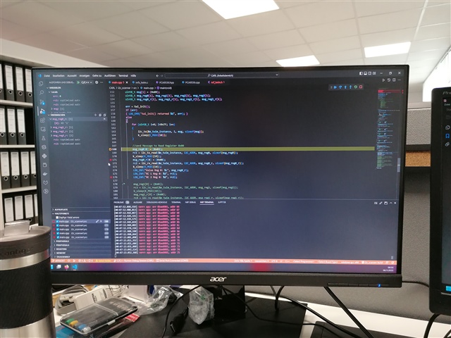
[00:00:09.736,724] <err> i2c_nrfx_twim: Error 0x0BAE0001 occurred for message 0
[00:00:09.736,938] <err> i2c_nrfx_twim: Error 0x0BAE0001 occurred for message 0
[00:00:09.737,121] <err> i2c_nrfx_twim: Error 0x0BAE0001 occurred for message 0
[00:00:09.737,304] <err> i2c_nrfx_twim: Error 0x0BAE0001 occurred for message 0


The Project-Copy:

I2C-Test.zip

Thanks for Help

Parents
  • Hello,

    Ketil asked if I could have a look at this ticket. 

    Can you please test the attached application:

    It is configured to use the nRF52833 DK and scan through all I2C addresses. So it is not aware of any particular I2C devices/addresses. Only a basic I2C configuration.

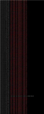
    It should print a lot of errors, but if one or more devices are connected via I2C on the pins (SDA pin P0.03 and SCL pin P0.04), then one of the lines should be an <inf> instead of <err>, and it should say FOUND DEVICE at the end of the line:

    If you can run this test, we can find out whether it is a SW or a HW issue.

    Best regards,

    Edvin

  • Hello Björn,

    So when you are able to write to the device on addr. 0x41, does the voltage look correct on the oscilloscope?

    BR,
    Edvin

  • Hallo Edvin,

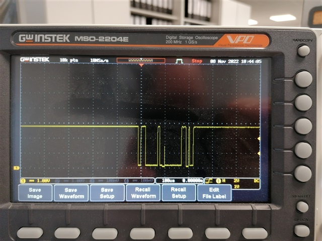
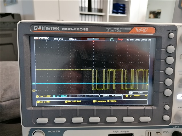
    now i get the oscilloscope measurment and now the voltages looks good.

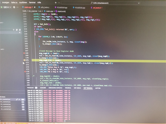
    Programcode write:

    osciloscope

    programcode read:

    osciloscope

    The Read Value of the register 3 of the PCA9536, that is used for write/read, has the value: 255 (0xFF, 0xb1111 1111). This is correct or a not configured PCA9536.

    I have a still question, what is the reason that the manual configured twim work and the automated configuration over the I2C-API don't work.

  • Hello,

    I am not sure exactly why it doesn't work, but it suggests that there are some issues in the configuration that you were using. 

    In your snippets from your original post:

    	gyro_adc@40 {
    		compatible = "i2c-device";
    		reg = < 0x40 >;
    		label = "gyro";
    	};
    	bq35100@55 {
    		compatible = "i2c-device";
    		reg = < 0x55 >;
    		label = "bms";
    	};*/

    I see that you are setting the addresses and labels, but what does "i2c-device" refer to? It is not something that is part of NCS by default, I think. Something that may cause the voltage to drop like that is if the devices are configured with wrong pull resistors. Did you set pull-down somewhere in the "i2C-device" settings?

    BR,

    Edvin

  • Hello Edvin,

    The compatile "i2c-device" is a generic-description this is usesd in every I2C-Driver, in the most cases at the second or third layer of the driver.

    I can't see any option in the pin-control section of the Overlay-file for I2C to set the resistors. at the UART i see the option to pull up the PIN (Section copy from the sample Project):

    &pinctrl {
    	i2c0_default: i2c0_default {
    		group1 {
    			psels = <NRF_PSEL(TWIM_SDA, 0, 26)>,
    				<NRF_PSEL(TWIM_SCL, 0, 27)>;
    		};
    	};
    
    	i2c0_sleep: i2c0_sleep {
    		group1 {
    			psels = <NRF_PSEL(TWIM_SDA, 0, 26)>,
    				<NRF_PSEL(TWIM_SCL, 0, 27)>;
    			low-power-enable;
    		};
    	};
    
    	uart0_default: uart0_default {
    		group1 {
    			psels = <NRF_PSEL(UART_TX, 0, 6)>,
    				<NRF_PSEL(UART_RTS, 0, 5)>;
    		};
    		group2 {
    			psels = <NRF_PSEL(UART_RX, 0, 8)>,
    				<NRF_PSEL(UART_CTS, 0, 7)>;
    			bias-pull-up;
    		};
    	};

    Best regards Björn

  • Hello Björn,

    Sorry for not being able to pin point exactly what is causing the voltage drop right away, but I see that most cases where the NCS SDK (including Zephyr) uses:

    compatible = "i2c-device"

    it actually says:

    compatible = "vnd,i2c-device"

    It is at least worth a shot. 

    So the measurements with the voltage drop, is that done with a DK or a custom board?

    What happens if you detach whatever is connected to the I2C bus. What voltage does the pin have then?

    Is there some way for me to reproduce what you are seeing on a DK without any external HW?

    BR,
    Edvin

Reply
  • Hello Björn,

    Sorry for not being able to pin point exactly what is causing the voltage drop right away, but I see that most cases where the NCS SDK (including Zephyr) uses:

    compatible = "i2c-device"

    it actually says:

    compatible = "vnd,i2c-device"

    It is at least worth a shot. 

    So the measurements with the voltage drop, is that done with a DK or a custom board?

    What happens if you detach whatever is connected to the I2C bus. What voltage does the pin have then?

    Is there some way for me to reproduce what you are seeing on a DK without any external HW?

    BR,
    Edvin

Children
  • Hello Edvin,

    all measurments are currently done with a DK Board, the custom Boards are in production.

    To the Driver compatible, i check the yaml-Drivers Files and see it in the first version. Only at specific Drivers the vnd shows the shortname of the producer. For a Basic-Driver-Componentlike I2C, i don't found anything in the "vnd, driver" notaition.

    I will tomorrow check the DK Board with out a device.

    Best Regards,

    Björn

  • Hallo Edvin,

    i have check the DK-Board, without any external Device and have the same Problem, but the Project-Partner has checed in this Time the differences between Zephyr-I2C-API and Nordic-TWIM-API. The Zephyr-API disable at the end of a transmission the TWI-Interface.This Produce by undefined Powerlevel of the Interface-Pins the Undefined Voltage-Level.

    So we test the DTS - PINCTL - Parameter "bias-pull-up" to solve the undefined Powerlevel for the Interface.

    Afterthis we can now find all Device at the Bus.The I2C-Devices at the Bus are, so it looks for me, Bus-Power sensitive. They need a defined Bus-Volatage-Level to work correctly.

    Best Regards

    Björn

Related