Need help with battery example

OK, this will no doubt be an easy one.  I'm playing around with the zephyr/samples/boards/nrf/battery example, as I have a need for something similar in my own application.  My environment is:

  • Visual Studio Code with nRF Connect extension
  • nRF Connect V2.0.0
  • nRF52-DK

But I'm having issues with getting the ADC measurement actually working.

Following the recommendations outlined here, I set up an overlay file as follows:

/ {
    zephyr,user {
       io-channels = <&adc 0>;
    };
 };

Goal here was to have AIN0 (which is connected to P0.02) on my hardware as the ADC input channel, as this aligns with my custom board that this code will ultimately be developed for.  However, I'm not seeing any change on the reported mV value despite changes in the actual voltage being applied to P0.02.

I'm guessing my allocation of the ADC channel isn't correct, but I can't find anywhere that clearly explains how this is configured for the nRF Connect environment.

Cheers,

Mike

Parents
  • Hi there MIke,

    I think that would setup the DK to use AIN0 and channel 0.

    The ADC examples sets the device to use the same pin number as the channel here

    If you want to use AIN2 and channel 0 then you have to set this line in the example to SAADC_CH_PSELP_PSELP_AnalogInput2 and omit "+ iocp->channel". 

    regards

    Jared 

  • Hi Jared,

    That was actually my objective - to use AIN0.  I didn't realise that I also have to specify a channel though.  I probably need to understand a bit more about the SAADC function and how channels work - can you point me to some documentation that explains this part of it?

    Looking at the battery.c code, I was able to see what the issue is.  In this snippet:

    if (cfg->output_ohm != 0) {
    		accp->input_positive = SAADC_CH_PSELP_PSELP_AnalogInput0
    			+ iocp->channel;
    	} else {
    		accp->input_positive = SAADC_CH_PSELP_PSELP_VDD;
    	}

    its basically setting the analog positive input channel to equal VDD if I haven't added the vbatt definition to my overlay file.  Which explains why the output of the example code was sitting unchanged at ~ 3V even though I was varying the analog signal at P0.02.

    I added the following to my overlay file:

     / {
        vbatt {
           compatible = "voltage-divider";
           io-channels = <&adc 0>;
           output-ohms = <150000>;
           full-ohms = <(1500000 + 150000)>;
           //power-gpios = <&sx1509b 4 0>;
        };
     };

    And changed this section of battery.c:

    f (cfg->output_ohm != 0) {
    		accp->input_positive = SAADC_CH_PSELP_PSELP_AnalogInput0;
    			//+ iocp->channel;

    And now its working as I would expect.

    One other question - the power-gpios is an optional parameter in the vbatt node.  What actually is that for?  I've just commented it out in my application, but I'd like to understand what it does

    Regards,

    Mike

  • Hi Mike,

    Great, that you found the solution!

    Mike Austin (LPI) said:
    One other question - the power-gpios is an optional parameter in the vbatt node.  What actually is that for?  I've just commented it out in my application, but I'd like to understand what it does

    From here,

    power-gpios:
    type: phandle-array
    required: false
    description: |
    Control power to the voltage divider inputs.
    If present the corresponding GPIO must be set to an active level
    to enable the divider input.

    To be honest, I haven't really used this child node before so not entirely sure how it's used. 

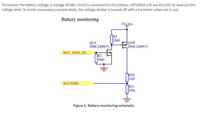
    EDIT: Actually, I found a use case where this child node would have been used. For example on our Thingy:52 we have a signal called BAT_MON_EN that "turns off" the voltage divider when it's not in use:

    regards

    Jared 

  • Thanks Jared.  Think the penny dropped for me about the same time you sent that explanation through.

    I've actually got a similar circuit set up on my custom board, except I'm using P0.30 as my BAT_MON_EN signal, and at the moment I have two 150K resistors as my resistor divider network.

    So, I modified my overlay file to this:

    / {
        vbatt {
           compatible = "voltage-divider";
           io-channels = <&adc 0>;
           output-ohms = <150000>;
           full-ohms = <(150000 + 150000)>;
           power-gpios = <&gpio0 30 (GPIO_PULL_DOWN | GPIO_ACTIVE_HIGH)>;
        };
     };

    And everything works as expected

    Thanks again

    Mike

Reply
  • Thanks Jared.  Think the penny dropped for me about the same time you sent that explanation through.

    I've actually got a similar circuit set up on my custom board, except I'm using P0.30 as my BAT_MON_EN signal, and at the moment I have two 150K resistors as my resistor divider network.

    So, I modified my overlay file to this:

    / {
        vbatt {
           compatible = "voltage-divider";
           io-channels = <&adc 0>;
           output-ohms = <150000>;
           full-ohms = <(150000 + 150000)>;
           power-gpios = <&gpio0 30 (GPIO_PULL_DOWN | GPIO_ACTIVE_HIGH)>;
        };
     };

    And everything works as expected

    Thanks again

    Mike

Children
Related