Pinctrl configuration

Hi.

I am working on the nRF Connect 2.0.0 SDK.

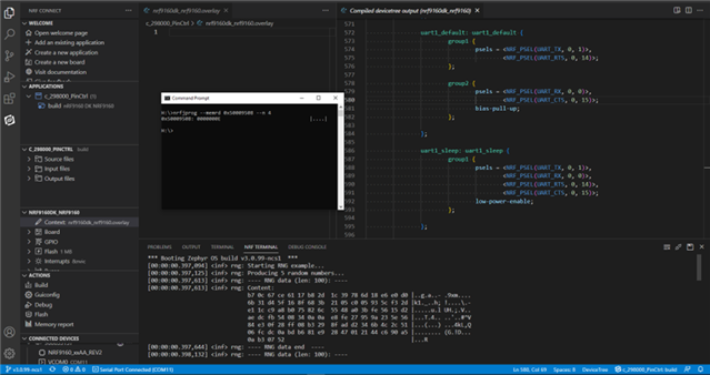
In the nrf9160dk_nrf9160_common-pinctrl.dtsi file the UART is configured with a CTS and RTS pin connected to a GPIO like this:

&pinctrl {
    uart1_default: uart1_default {
		group1 {
			psels = <NRF_PSEL(UART_TX, 0, 1)>,
				<NRF_PSEL(UART_RTS, 0, 14)>;
		};
		group2 {
			psels = <NRF_PSEL(UART_RX, 0, 0)>,
				<NRF_PSEL(UART_CTS, 0, 15)>;
			bias-pull-up;
		};
	};

	uart1_sleep: uart1_sleep {
		group1 {
			psels = <NRF_PSEL(UART_TX, 0, 1)>,
				<NRF_PSEL(UART_RX, 0, 0)>,
				<NRF_PSEL(UART_RTS, 0, 14)>,
				<NRF_PSEL(UART_CTS, 0, 15)>;
			low-power-enable;
		};
	};

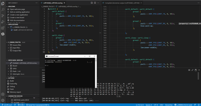
In the overlay file I change it to:

&pinctrl {
    uart1_default {
		group1 {
			psels = <NRF_PSEL(UART_TX, 0, 30)>;

		};	
		group2 {
			psels = <NRF_PSEL(UART_RX, 0, 31)>;
		};
	};

	uart1_sleep {
		group1 {
			psels = <NRF_PSEL(UART_TX, 0, 30)>,
				<NRF_PSEL(UART_RX, 0, 31)>;
			low-power-enable;
		};
	};

With the configuration in the overlay file without CTS and RTS configuration, will the RTS and CTS pins be disconnected from the GPIOs or will they be connected to they be connected to the GPIOs from the configuration in the .dtsi file?

If the CTS and RTS is still connected to the GPIOs, how do I disconnect them?

  • Hi Simen,

    Thank you for contacting DevZone at NordicSemi. 

    I have been assigned this ticket, and I will look into the case and will update you on Monday hopefully.

    Regards,

    Naeem

  • Hi Simen,

    Thank you for your patience. 

    So basically, your query is about disconnecting the CTS and RTS.

    I started with a sample example for your board.

    Here I would like to show compiled-DTS and ad the output from the register PSEL.RTS using the nRF JPROG (command line tool). I am not using overlay (an empty overlay initially). You can see that the value of PSE.RTS register is 0x0000000E which is referring that RTS pin is 14 and is connected (MSb=0 means connected, and MSb=1 means disconnected). Please see the product specification document for these details.

    Next, I used the overlay file as you are using, and you can see in the image below that DTS does not contain RTS pin for UART1, and the value from PSEL.RTS is 0xFFFFFFFF which means that the register is RESET, and the RTS is disconnected.

    Hope it helps.

    Regards, 

    Naeem

  • In the later versions of the (I'm using v2.5.0), RTS and CTS still remains connected after removing them from pinctrl in the overlay file.

    I had to explicitly disconnect them using NRF_PSEL_DISCONNECTED


Related