I've been trying to track down why we have higher than expected current consumption in our application. This is on custom hardware using an nRF5340 module, powered in High Voltage Mode (i.e. power supply connects to HVCC and not VCC) at 3 volts. Also worth noting we are powering some external chips off VCC, but they should be drawing only a few uA each.
Eventually I found that we have ~800 uA more current on our hardware than we do on a Dev Kit, even if we do very little in terms of code running on the device. The difference being, it would seem, that the Dev Kit is in Normal Voltage Mode, and our board is in High Voltage Mode. By connecting HVCC and VCC (as far as I can tell, this is all I need to do to put the chip into normal voltage mode) I get very much lower current consumption - our actual code goes from ~1300 uA to ~500 uA, and the test code I've been using goes from ~900 uA to ~100 uA. So it seems like the VREGH is somehow drawing 800 uA.
Is this expected, perhaps because we're powering at only 3 volts? Or have I missed something simple that we need to do in configuration to correctly enable High Voltage mode?
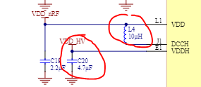
I believe the module we're using has all the inductors and capacitors needed for High Voltage Mode, but perhaps we missed something and it doesn't - could that be the cause?
Or does the nRF5340 not support external components powered via VCC? I did see something earlier about an nRF52 chip that didn't, which made me wonder.
The obvious fix is to just use normal voltage mode instead, but I'd be happier with this if I could explain why there's such a big difference.