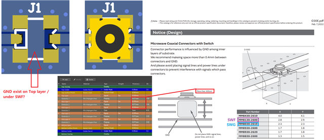
Hi guys. I was observing the PCA10121 PCB layout using this link.
Schematic for PCA10121 nRF5340 Audio DK
From Murata SWF connector datasheet, it says
Connector performance is influenced by GND among inner layers of substrate.
We recommend making space more than 0.4mm between connectors and GND.

In case of PCA10121, to follow Murata's 400um keepout rule, which layers are removed under J1 (MM8130-2600)? Is it
Dielectric 1 + Mid layer 1 + Dielectric 2 + Mid layer 2 = total 212um? OR
Dielectric 1 + Mid layer 1 + Dielectric 2 + Mid layer 2 + Dielectric 3 = total 1212um?
Also, under J1, the Top layer GND can be kept, right?
Lastly, SWF datasheet doesn't show the insertion loss after 6 GHz.
Is the SWF or SWG reliable when measuring 2nd, 3rd, 4th, ... harmonics? I know one Nordic Thread recommended UFL connectors
SWF connector for customized PCB
but I would like to use SWF due to the convenient feature of this connector so I'd like to hear your tips and what accuracy were observed.
Thank you so much!
