Murata SWF accuracy and PCB layout question

Hi guys. I was observing the PCA10121 PCB layout using this link.

 Schematic for PCA10121 nRF5340 Audio DK 

From Murata SWF connector datasheet, it says

https://www.murata.com/-/media/webrenewal/support/library/catalog/products/connector/o30e.ashx?la=en-gb&cvid=20220210015534000000

Connector performance is influenced by GND among inner layers of substrate.

We recommend making space more than 0.4mm between connectors and GND.

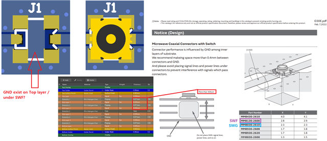
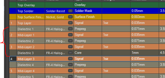
In case of PCA10121, to follow Murata's 400um keepout rule, which layers are removed under J1 (MM8130-2600)? Is it

Dielectric 1 + Mid layer 1 + Dielectric 2 + Mid layer 2 = total 212um? OR

Dielectric 1 + Mid layer 1 + Dielectric 2 + Mid layer 2 + Dielectric 3 = total 1212um?

Also, under J1, the Top layer GND can be kept, right?

Lastly, SWF datasheet doesn't show the insertion loss after 6 GHz.

Is the SWF or SWG reliable when measuring 2nd, 3rd, 4th, ... harmonics? I know one Nordic Thread recommended UFL connectors

 SWF connector for customized PCB 

but I would like to use SWF due to the convenient feature of this connector so I'd like to hear your tips and what accuracy were observed.

Thank you so much!

Parents
  • Hi,

    Seems you have the latest version of the HW files for the Audio DK, but you can always find the files you need for our products on the product page download section. So adding the link to the download section here just as a reference for future: https://www.nordicsemi.com/Products/Development-hardware/nRF5340-Audio-DK/Download?lang=en#infotabs

    Dielectric 1 + Mid layer 1 + Dielectric 2 + Mid layer 2 + Dielectric 3 = total 1212um?

    this would be the correct way to measure the distance.1.212um. 


    Also, under J1, the Top layer GND can be kept, right?

    From the datasheet you can see that GND is directly under the connector on the top layer, so following the datasheet this can be kept.

    As for what impact it would have to not include the top layer GND i am not certain so this might be something that the manufacturer can answer better or if someone else has done any experiments with this that can comment in more extent.


    Is the SWF or SWG reliable when measuring 2nd, 3rd, 4th, ... harmonics? I know one Nordic Thread recommended UFL connectors

    From the simple testing i have done with SWF and adapter wire\connector and compared to the results form directly connecting a coaxial cable to the RF line when measuring the output from the radio there has not been any major differences two the harmonics as i can recall. There is some extra loss when using extra converters\adapters but that can be adjusted for.


    But if your are looking for third party antennas with the SWF connector that might be difficult so so then a UFL is more common and makes more sens to use. Think that is mostly feedback in the other ticket you referenced. As that customer wanted to use external antenna.


    Regards,
    Jonathan

  • Thank you so much Jonathan! One additional question before closing this please.

    I'm only using the SWF connector to measure the RF using the spectrum analyzer. No 3rd party antennas will be involved.

    From the SWF connector's datasheet, is says "DC to 6GHz". When you said

    "there has not been any major differences two the harmonics as i can recall."

    the 3rd (7200 MHz) and above harmonics are still readable, even though the datasheet says DC to 6GHz, right?

    May I ask the amount of "difference" you observed? Even a rough number is greatly appreciated!

    EX: Spectrum analyzer read -50 dBm at 7206 MHz and 9608 MHz when using the UFL (with RBW = 100 kHz etc)

    VS

    Spectrum analyzer read -49 dBm at 7206 MHz and 9608 MHz when using the SWF connector


    For me, this "DC to 6GHz" range was always got into my mind when measuring.

  • I don't have any concrete number, but i can do some test if that is of interest to you, i will only be able to compare SWF with coaxial probe, and not a UFL connector.  But using a UFL connector that is rated up to rated up to 12GHz or higher is probably the "correct" choice. But that is a bit more inconvenient as you would have t change the layout.

    Regards,
    Jonathan

  • Thank you Jonathan. No need to rush regarding the "compare SWF with coaxial probe" experiment.

    I can wait for your results. Greatly appreciate your time and investigation!

Reply Children
  • Hi,

    So did some quick tests just to see if there was much of a difference and provide some numbers. 

    Adding a power point with the plots, only for channel 40 with +4dBm. I did not adjust for the difference in loss with the two connection types, but a quick comparison between the delta variation of each "connector" seem to show that they perform about the same. Wit the setup we use when we do tuning on customer products. 


    SWF connecotr VS Coaxial probe.pptx


    The coaxial probe was connected to the same pad that the SWF connector is connected to, so physically on the PCB the connectors where on the same location. 


    So for testing and inspecting it is ok, but for official certification high accuracy measurements then I would go for a connector that is rated for the task specifically. 

    I can do some more if you have anything specific in mind. 

    Regards,
    Jonathan

  • Thank you Jonathan. May I ask what the part number of the coax cable and the SWF cable you used?

    Hope I can buy those from Mouser or Digikey so that I can be in the same page.

    Also, how about this:

    Using PCA10056 / nRF52840 revision 3, comparing SWF vs coaxial probe at the same location,

    https://infocenter.nordicsemi.com/topic/comp_matrix_nrf52840/COMP/nrf52840/nRF52840_ic_revision_overview.html

    TX HARMONICS TEST at Channel 39 2480 MHz +8dBm:

    can we test this to the 8th harmonics if possible, comparing SWF vs coax?

    Next,

    RX PER SENSITIVITY TEST at 2480 MHz / try 1M & 2M PHY / 1500 number of packets or more

    How about reducing power level until either reaches 30.8 %?

    EXAMPLE for 2480 MHz 2M PHY:

    30.8% PER is reached with -92 dBm when using SWF

    VS

    30.8% PER is reached with -95 dBm when using coax

    No need to rush if you need time to prepare Spectrum analyzer and Anritsu Bluetooth tester etc.

    Take your time and greatly appreciate your help!

  • Matthew K said:
    May I ask what the part number of the coax cable and the SWF cable you used?

    me make the coax probes so no part number for that specifically, but we use the SMA, so 11_SMA-50-2-15/111_NE . And for the coaxial cable we use this : https://www.ezform.com/product/ez-47m17-2/ .

    SWF is the MM8130-2600 from murata: https://www.murata.com/en-global/products/connector/switchconnector/overview/lineup/swf , you can check the BOOM of our DK's, they have all part numbers listed. 

    But then there is also the converter\adapter https://www.digikey.no/en/products/detail/murata-electronics/MXHS83QE3000/1775923 when using the SWF. 


    Matthew K said:
    can we test this to the 8th harmonics if possible, comparing SWF vs coax?

    8th harmonic is very high, any reason for this specifically? We don't have the option to check 8th harmonic whit the current available lab equipment. 

    I can do the test on the PCA10056 / nRF52840 revision 3. 


    Matthew K said:
    RX PER SENSITIVITY TEST

    Not sure what additional benefit this info would provide other then being able to compare the two setups. Knowing the loss of the SWF connector should be enough to see how accurate the values you are measuring is. 

    Seems to me like you are looking for the loss in the SWF connector over a wider frequency range then what is listed in the datasheet. You can try to contact Murata for more details.  


    I would only be concerned about the accuracy of the SWF connector if you are close to the limits of certain certifications or some specific criteria. 

    Regards,
    Jonathan

  • Hi Jonathan About "8th harmonic is very high, any reason for this specifically?"

    As you mentioned, I was looking for the loss in the SWF connector over a wider frequency range then what is listed in the datasheet. Just wondering if your team have experimented with high frequency ranges.

    From your presentation, is your spectrum analyzer can measure around 15 GHz max (near the 5th 12.2 GHz)?

    If that's the case, you are right: I should ask this to Murata.

    Thanks for looking into this!

  • Matthew K said:
    From your presentation, is your spectrum analyzer can measure around 15 GHz max (near the 5th 12.2 GHz)?

    Currently using a Rohde Schwarz signal analyzer (FSV3013) that goes up to 13.6GHz so 8th harmonic is outside of its range. 

    Were looking in to higher frequency stuff as WIFI is something we are going to be working on with the nRF7002 release so in a year we might be better equipped to handle these kinds of requests. 

    Regards,
    Jonathan

Related