Measurement ranges and switch levels

Hi Madam/ Sir,

I am using your PPK II to measure current consumption. Based on your document, this device use an internal resistor to measuring current. And the PPK features three calibrated parallel measurement means realizing the three measurement ranges simultaneously. I would like to know the value of the resistor that is chosen in theses three measurement ranges, could you please tell me the resister value during measurement?

I would like to measure the current between 15 mA  and 5mA. I prefer to have a fixed resistor and I would like to know it's value. 

Is it possible to use just one switch level without switching between these levels?

Best Regards,

Maryam 

  • Hi Maryam,

    Thank you for your request. We will look this up and get back to you.

    Best regards,

    Håkon

  • Hi Hakon, 

    Very mrch thanks.

    Best Regards,

    Maryam 

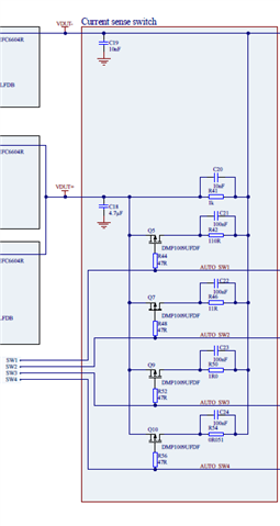
  • I believe the resistor you are asking for is R42, which is 110 Ohms.

    The schematics for PPK2 can be found on our website.

    The PPK2 is selecting automatically between the resistors. However, you could try to modify the boards by manipulating SW1, SW2, SW3, SW4 to turn on and off the loads.

    Here is a description of the Measurement system from the PPK2 user guide:

    The Power Profiler Kit II (PPK2) is driven by the nRF52840 System on Chip (SoC), which uses its analog-to-digital converter (ADC) to measure a voltage drop over a series of measurement resistors. Resistor values are used to calculate the power consumption. The PPK2 has five different measurement ranges, which are managed by an automatic switch circuitry.

    The Measurement accuracy is specified for the various ranges:

    Name Range Typ Description
    R1_Accuracy 100 nA–50 µA ± 10% Readout on average value
    R1_Offset ± 2%  
    R2_Accuracy 50 µA–500 µA ± 10% Readout on average value
    R2_Offset ± 2%  
    R3_Accuracy 500 µA–5 mA ± 10% Readout on average value
    R3_Offset ± 2%  
    R4_Accuracy 5 mA–50 mA ± 10% Readout on average value
    R4_Offset ± 2%  
    R5_Accuracy 50 mA–1000 mA ± 15% Readout on average value
    R5_Offset ± 5%  

    Table 1. Measurement accuracy

    Does this answer your questions?

  • Hi,

    I appreciate your response.

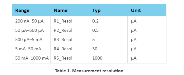
    Based on the schematic there are 4 paths that changes the value of the resistor baes on the current value to measure the current. I found that the R42 parallels with R41 is used when the value of the current  measurement is around 5m A~ 50 mA. I would like to map these resistors consisting of R42,R46,R50,R54  with the measurement resolution table. Maybe the name of the R1_Resol and R2_Resol , so on should be change by R42,R46,R50,R54 in order to understand which resistors used in each current range.

    Could you help me to understand which resistors is used for different current ranges?


    And, one thing more, how can modify theses switch manually? Can I fixed this switch to SW4 ?

    Best Regards,

    Maryam 

  • Hi,

    You can adjust the gain by pressing ALT-SHIFT-CTRL-A in the nRF Connect Desktop app but this is not recommended for normal usage. The resistors in the measurement resolution isn't directly corresponding to a specific resistor in the schematic, and you are not meant to modify them directly. Instead you can configure the gain by adding an offset to the gain settings. For example if you notice that you have an offset when you measure current in the 200 nA to 50 µA range, then you can configure Range 1 in the gain settings. Only using one level without switching is not supported as far as I know.

    regards

    Jared 

Related