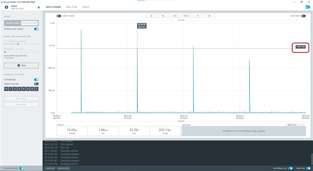
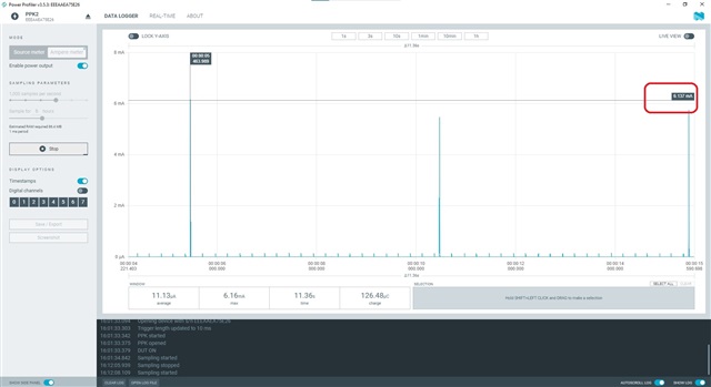
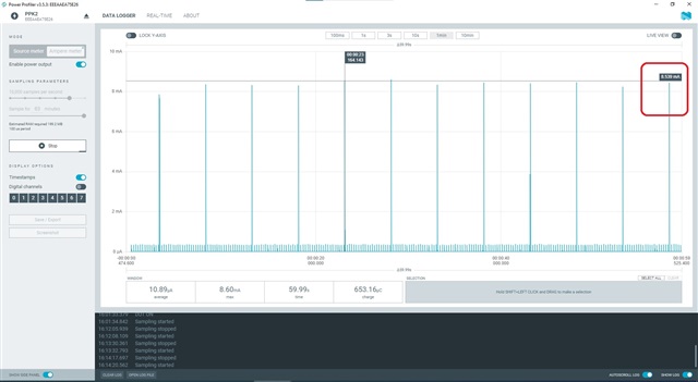
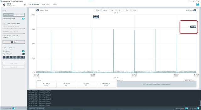
PPK2 showing Different current reading on different sampling rate settings

I have connected BLE device to the Nordic's power profiler kit 2 to do power analysis.

My BLE device advertises every 5 seconds.

I can see current consumption spike every 5 sec in Power profiler waveform.

First I saw waveform with 100 sample per seconds setting.

After that I analyzed after changing the sampling rate to 1000 samples per seconds.

I saw that current value measured by analyzer changes proportionally as I increase the sampling rate setting.

Please help me to understand what is the actual current being consumed by my device?

For reference this the table of actual measured values.

Samples/Seconds setting Measured Current
100 1.4mA
1000

6.1mA

10000 8.5mA

100 000

15.5mA

Thank you

Dnyaneshvar

  • Hi Dnyaneshvar,

    I will look into this and get back to you.

  • Hi Dnyaneshvar, sorry for the delay.

    The average current consumption is the most important measurement to pay attention to. If you sample with at a high sample rate and read out maximum current, you get to see where the largest current spikes are. If you sample at a lower sample rate, then the largest spikes will have been averaged out over the sample interval. This will result in the maximum current displayed as lower than for high sample rate. The average current is still very similar.

    The schematics for PPK2 can be found on our website if you would like to take a closer look.

    Hope this answers your question.

  • Hi ,

    1) The average current consumption is the most important measurement to pay attention to.  - Okay.

    2) If you sample at a lower sample rate, then the largest spikes will have been averaged out over the sample interval.

    This will result in the maximum current displayed as lower than for high sample rate.- I am talking about the instantaneous values of current. Instantaneous current consumed by advertising interval of load device. It can be clearly seen that it's values measured by PPk2 are all different at four different sampling rate.

    Yes, Averaging is done with respect to the sampling frequency, I agree.

    Increasing sampling rate would result in increase in the accuracy of measured parameters.

    But how come the value of instantaneous current consumed become different for different sampling rate.

    How the current of 1.4mA becomes 15.5mA when sampling frequency changes from 100 to 100 000 samples per seconds?

  • Hi Dnyaneshvar,

    I took over this case from Håkon who is out of office.

    dnyaneshvar said:
    How the current of 1.4mA becomes 15.5mA when sampling frequency changes from 100 to 100 000 samples per seconds?

    When the sampling frequency decreases, the reported instantaneous current is based on the average over a longer period. If you have very short spikes which are shorter than the sampling period, you will not be able to measure the maximum.

    The length of the TX and RX peaks are in the 100 us range, hence you will need a sampling frequency of 20000 samples per second or higher in order to capture the TX or RX peak current. If you zoom in on the advertising interval at 100000 samples per seconds, it will probably be more clear, and easier to see what the advertising event actually consists of.

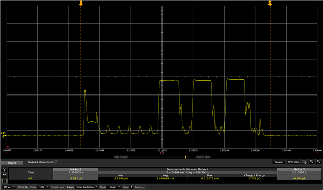
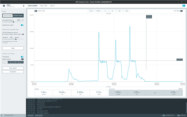
    When that is said, the PPK2 sometimes shows current spikes when the current range switches. This is an artifact from the PPK2 itself and is not part of the actual current. Here is an advertising event measured with a professional lab equipment compared with the PPK2:

    The radio TX peak current is the flat area at 6.3mA.

    The peaks will vary based on the load impedance, so it may look different when measuring on your board. Please note that the average current or the total charge over the advertising event will be correct. You can also compare the measurements with the online power profiler:  Online Power Profiler for Bluetooth LE 

  • Hello  ,

    When that is said, the PPK2 sometimes shows current spikes when the current range switches. This is an artifact from the PPK2 itself and is not part of the actual current. 

    By comparing the two Images above, I can see that there are current spikes in waveform measured by PPK2 kit and for same section measured by the professional tool mentioned by you, there isn't any current spikes.

    I don't have the sophisticated professional tool the one you are using (as of now at least).

    Currently I am limited to use PPK2 KIT only.

    So for waveforms other than mentioned above how can I identify the current spikes shown by PPK2 KIT are due to the artifact from the PPK2 itself and is not part of the actual current?

Related