NRF 52 OLED SSD 1306 SEGGER

Hello to all

I am quite lost, I need help to connect an oled to my project. The rest of the stages I have it complete, but my experience with OLED, is limited to arduino with U8G2 type libraries, that is, I don't know how to connect and configure my display with my board.

I am using NRF52DK and segger Studio.

Any recommendations on how I should start, or example with my environment?

Thank you very much

Parents
  • Hi Hakon

    Thank you for your reply.

    Can i use this example with segger Embedded Studio? ¿What advantage have nRF Connect SDK?

    Thank you

  • DBdani said:
    Can i use this example with segger Embedded Studio?

    Yes. You can use the example regardless of whether you choose to use Segger Embedded Studio, Visual Studio Code or command line. For building applications, Visual Studio Code with the nRF Connect for VS Code extension is our recommendation. For more information about the extension, see the nRF Connect for Visual Studio Code documentation page.

    DBdani said:
    ¿What advantage have nRF Connect SDK?

    nRF Connect SDK is our main SDK onward while the nRF5 SDK is in maintenance mode. Please see the nRF Connect SDK and nRF5 SDK statement for details. Which SDK you choose is up to you, however, we recommend nRF Connect SDK for all new projects as this is the SDK where fixes, updates and new features will be implemented.

    Also see the Introduction page at nRF Connect SDK documentation for details about nRF Connect SDK. Check out the getting started page for nRF Connect SDK as well as the mentioned Nordic Developer Academy.

  • I was able to reproduce the same or similar errors when trying to build without any overlay file.

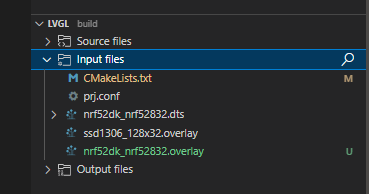
    Did you create any .overlay file? Check under input files if there is any such file.

    If not present, click where it says "Click to generate overlay". Then add the following to the generated(empty) file:

    &pinctrl {
        i2c0_default: i2c0_default {
            group1 {
                psels = <NRF_PSEL(TWIM_SDA, 0, 26)>,
                    <NRF_PSEL(TWIM_SCL, 0, 27)>;
            };
        };
    
        i2c0_sleep: i2c0_sleep {
            group1 {
                psels = <NRF_PSEL(TWIM_SDA, 0, 26)>,
                    <NRF_PSEL(TWIM_SCL, 0, 27)>;
                low-power-enable;
            };
        };
    };
    
    arduino_i2c: &i2c0 {
    	compatible = "nordic,nrf-twim";
    	status = "okay";
    	clock-frequency = <I2C_BITRATE_FAST>;   
        zephyr,concat-buf-size = <4096>;
      
        ssd1306: ssd1306@3c {
            compatible = "solomon,ssd1306fb";
            reg = <0x3c>; //0x3c is the i2c address of the SSD1306 aIC.
            width = <128>;
            height = <32>; // Change to '64' when using the 128x64 pixel version.
            segment-offset = <0>;
            page-offset = <0>;
            display-offset = <0>;
            multiplex-ratio = <31>; //change to '63' when using the 128x64 pixel version
            segment-remap;
            com-invdir;
            com-sequential;
            prechargep = <0x22>;
        };
    };
    	

    I selected i2c0 for nRF52 DK.

    Please report back how this goes.

    I tried building with nRF Connect SDK v2.1.2 but I did test it on the DK as I did not have any nRF52 DK at hand today. I will try flashing the board tomorrow.

  • Hello Helsing,

    Thank you for your reply

    I try to generate overlay file, and now i have two new problems:

    I'm lost with this issue.

    Thank you very much

  • Have you taken the shield into use? I am getting a similar error as you if I remove references to the ssd1306 shield. Try adding this line of code to the file CMakeLists.txt in your project folder: set(SHIELD ssd1306_128x32).

    Add the line just below cmake_minimum_required(VERSION 3.20.0).

  • Hello Helsing

    Thank you very much for your help.

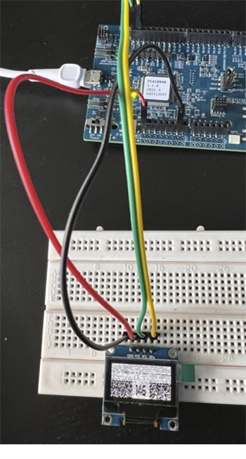
    Now, i can flash DK board, but i have any mistake, because the thisplay show this:

    GND-->GND

    VCC -->VCC

    SCL-->P0.27

    SDA-->P0.26

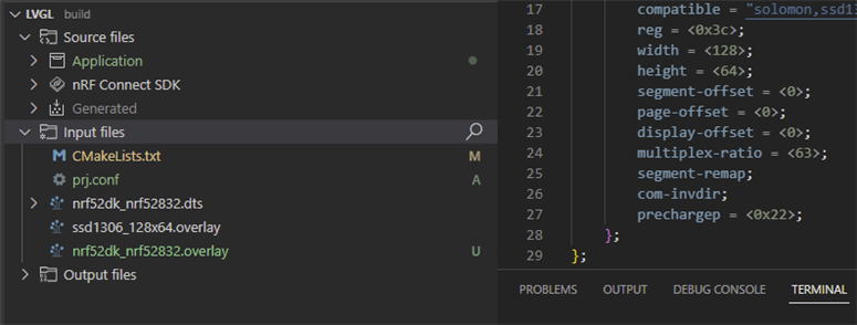
    I have this Structure now:

    With this code:

    (Overlay file)

    &pinctrl {
        i2c0_default: i2c0_default {
            group1 {
                psels = <NRF_PSEL(TWIM_SDA, 0, 26)>,
                    <NRF_PSEL(TWIM_SCL, 0, 27)>;
            };
        };
    
        i2c0_sleep: i2c0_sleep {
            group1 {
                psels = <NRF_PSEL(TWIM_SDA, 0, 26)>,
                    <NRF_PSEL(TWIM_SCL, 0, 27)>;
                low-power-enable;
            };
        };
    };
    
    arduino_i2c: &i2c0 {
    	compatible = "nordic,nrf-twim";
    	status = "okay";
    	clock-frequency = <I2C_BITRATE_FAST>;   
        zephyr,concat-buf-size = <4096>;
      
        ssd1306: ssd1306@3c {
            compatible = "solomon,ssd1306fb";
            reg = <0x3c>; //0x3c is the i2c address of the SSD1306 aIC.
            width = <128>;
            height = <64>; // Change to '64' when using the 128x64 pixel version.
            segment-offset = <0>;
            page-offset = <0>;
            display-offset = <0>;
            multiplex-ratio = <63>; //change to '63' when using the 128x64 pixel version
            segment-remap;
            com-invdir;
            com-sequential;
            prechargep = <0x22>;
        };
    };

    Cmakelist

    # SPDX-License-Identifier: Apache-2.0
    
    cmake_minimum_required(VERSION 3.20.0)
    set(SHIELD ssd1306_128x64)
    
    find_package(Zephyr REQUIRED HINTS $ENV{ZEPHYR_BASE})
    project(lvgl)
    
    FILE(GLOB app_sources src/*.c)
    target_sources(app PRIVATE ${app_sources})
    

    Thank you very much

  • Hi Daniel

    Sorry for the slow response. We have had limited staffing over Christmas. Håkon is currently unavailable and I will help you out in the mean time. 

    Are you just running the standard lvgl example without any changes? 

    Do you see the number getting updated, and can you read it correctly? 

    If I am not mistaken the standard example is not black and white, and the issues you see might just be caused by the black and white conversion. If this is the case it should be enough to ensure that all the LVGL elements are either black or white, rather than some other colors. 

    Best regards
    Torbjørn

Reply
  • Hi Daniel

    Sorry for the slow response. We have had limited staffing over Christmas. Håkon is currently unavailable and I will help you out in the mean time. 

    Are you just running the standard lvgl example without any changes? 

    Do you see the number getting updated, and can you read it correctly? 

    If I am not mistaken the standard example is not black and white, and the issues you see might just be caused by the black and white conversion. If this is the case it should be enough to ensure that all the LVGL elements are either black or white, rather than some other colors. 

    Best regards
    Torbjørn

Children
  • Hello,

    I believe there is nothing to indicate the use of colors in the standard example. Please correct me if I am wrong. I still cannot use the screen correctly.

    The numbers do indeed advance, the problem is that they look wrong, with the screen full of random white pixels.

    Thank you

    /*
     * Copyright (c) 2018 Jan Van Winkel <[email protected]>
     *
     * SPDX-License-Identifier: Apache-2.0
     */
    
    #include <zephyr/device.h>
    #include <zephyr/devicetree.h>
    #include <zephyr/drivers/display.h>
    #include <zephyr/drivers/gpio.h>
    #include <lvgl.h>
    #include <stdio.h>
    #include <string.h>
    #include <zephyr/kernel.h>
    
    #define LOG_LEVEL CONFIG_LOG_DEFAULT_LEVEL
    #include <zephyr/logging/log.h>
    LOG_MODULE_REGISTER(app);
    
    static uint32_t count;
    
    #ifdef CONFIG_GPIO
    static struct gpio_dt_spec button_gpio = GPIO_DT_SPEC_GET_OR(
    		DT_ALIAS(sw0), gpios, {0});
    static struct gpio_callback button_callback;
    
    static void button_isr_callback(const struct device *port,
    				struct gpio_callback *cb,
    				uint32_t pins)
    {
    	ARG_UNUSED(port);
    	ARG_UNUSED(cb);
    	ARG_UNUSED(pins);
    
    	count = 0;
    }
    #endif
    
    void main(void)
    {
    	int err;
    	char count_str[11] = {0};
    	const struct device *display_dev;
    	lv_obj_t *hello_world_label;
    	lv_obj_t *count_label;
    
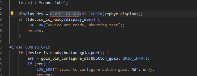
    	display_dev = DEVICE_DT_GET(DT_CHOSEN(zephyr_display));
    	if (!device_is_ready(display_dev)) {
    		LOG_ERR("Device not ready, aborting test");
    		return;
    	}
    
    #ifdef CONFIG_GPIO
    	if (device_is_ready(button_gpio.port)) {
    		err = gpio_pin_configure_dt(&button_gpio, GPIO_INPUT);
    		if (err) {
    			LOG_ERR("failed to configure button gpio: %d", err);
    			return;
    		}
    
    		gpio_init_callback(&button_callback, button_isr_callback,
    				   BIT(button_gpio.pin));
    
    		err = gpio_add_callback(button_gpio.port, &button_callback);
    		if (err) {
    			LOG_ERR("failed to add button callback: %d", err);
    			return;
    		}
    
    		err = gpio_pin_interrupt_configure_dt(&button_gpio,
    						      GPIO_INT_EDGE_TO_ACTIVE);
    		if (err) {
    			LOG_ERR("failed to enable button callback: %d", err);
    			return;
    		}
    	}
    #endif
    
    	if (IS_ENABLED(CONFIG_LV_Z_POINTER_KSCAN)) {
    		lv_obj_t *hello_world_button;
    
    		hello_world_button = lv_btn_create(lv_scr_act());
    		lv_obj_align(hello_world_button, LV_ALIGN_CENTER, 0, 0);
    		hello_world_label = lv_label_create(hello_world_button);
    	} else {
    		hello_world_label = lv_label_create(lv_scr_act());
    	}
    
    	lv_label_set_text(hello_world_label, "Hello world!");
    	lv_obj_align(hello_world_label, LV_ALIGN_CENTER, 0, 0);
    
    	count_label = lv_label_create(lv_scr_act());
    	lv_obj_align(count_label, LV_ALIGN_BOTTOM_MID, 0, 0);
    
    	lv_task_handler();
    	display_blanking_off(display_dev);
    
    
    }
    

Related