Hi Nordic,
When I was using NRF52840 for FCC certification, the DTM 8dBm, 2Mbps sideband emission power exceeded the standard.
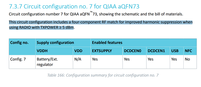
The antenna matching circuit is to use the parameters recommended by Nordic engineer.
In addition to reducing the transmit power, is there another way to modify the parameters and make the test pass?
In the actual test, I set DTM 8dBm, some PCBA output can reach 9.2dBm, some only 7.5, their consistency is not very good.Is this a chip difference or something else?
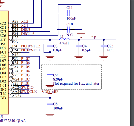
RF schematic
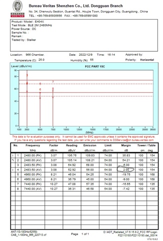
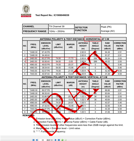
Sideband exceeded the standard
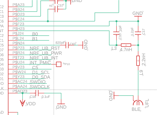
RF BOM
|
C10
|
CAP CER 1PF±0.05pF 50V C0G/NP0 0402
|
Murata Electronics
|
GJM1555C1H1R0WB01D
|
|
C17
|
Cap Ceramic 1.2pF ±0.05pF 50V C0G 0.05pF Pad SMD 0402 125°C T/R
|
Murata Electronics
|
GJM1555C1H1R2WB01D
|
|
L3
|
FIXED IND 4.7NH +/-0.1NH 700MA 160MOHM 0402
|
Murata Electronics
|
LQG15HS4N7B02D
|
|
L9
|
FIXED IND 2.2NH 900MA 90MOHM SMD
|
Murata Electronics
|
LQG15HS2N2B02D
|
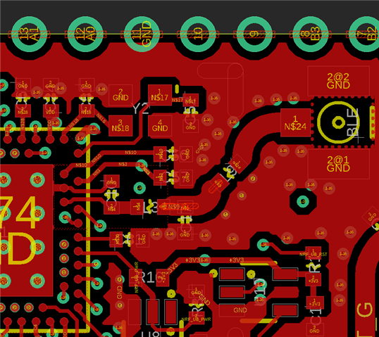
Top layer
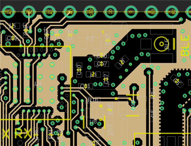
Layer2
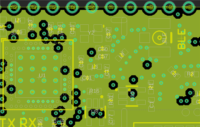
Layer3 GND