NRF24LE1

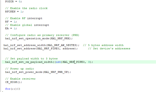
Hello, first of all, I am an engineering student. I want to learn communication and I just started it. I don't understand exactly what the following lines do. How can I do? What are the current resources? I couldn't understand the following lines of code.... Waiting for your support. ((The codes are completely taken from (enhanced_shockburst_ptx_nrf24le1.uvproj))

What part of the code does the actual work? Where is the ACK part? I don't want ACK and I want to work at 1 Mbps.

I don't know about addressing either, I don't know where to start :)

Thank you from now...

Parents
  • Hi

    I don't know what you mean by the "actual work"? 

    In the nRF24LE1 the radio core handles the ESB protocol for you, all the application has to do is to write to the configuration registers, write a payload, and raise the CE line for 10 microseconds to initiate a transfer. Essentially the nRF24LE1 is just the nRF24L01+ radio chip and an 8-bit MCU bundled together on the same chip, and if you read the datasheet of the nRF24L01+ and the nRF24LE1 you will see that the radio works more or less identically. 

    The NRF_ISR interrupt is triggered every time the radio raises its interrupt line, and this can happen either as a result of a successfully transmitted packet (TX_DS), a failed transmission (MAX_RT) or a reception of a packet (RX_DR). 

    All the code to the right is doing is to write a new TX payload over the internal SPI bus, raise the CE line for 10 microseconds to start the transmission, and wait for the operation to complete by waiting for the radio_busy flag to be cleared by the interrupt handler. 

    In order to disable ACK it should be sufficient to open your pipe with the auto_ack flag cleared using the hal_nrf_open_pipe function (this has to be done both on the TX and RX side):

    hal_nrf_open_pipe(HAL_NRF_PIPE0, false);

    The address in the radio has two primary purposes. On one hand it serves as a sync word, and allows the receiver to detect the start of a valid packet over the air. Secondly it allows different devices operating in the same area to coexist by having them use different addresses, so that a packet sent by one device will not be picked up by the wrong receiver. 

    Exactly what you set the address to is less important, just be aware that addresses with very few bit shifts are more challenging for the receiver to pick up and could lead to higher packet loss. 

    Best regards
    Torbjørn

  • ESB

    thank you

    What should I do to run at 1 mbps? How are address definitions made? Are there any sample codes for these?

  • Hi

    We do have an application note that includes some software examples showing how to use the ESB protocol in the nRF24L series devices (nRF24L01+, nRF24LE1 or nRF24LU1+).

    Please have a look at the appnote pdf and the included software examples here.

    In your case I believe it is the "sb" example that is most relevant. It uses the legacy ShockBurst protocol which doesn't send ACK packets. 

    The software examples show how the address and bitrate can be configured, in particular have a look at the radio_sb.c file which includes the radio setup for the ShockBurst example. 

    Best regards
    Torbjørn

  • I can communicate by entering the address on the TX and without touching the RX, but when I enter the address on the RX, I cannot communicate. I don't know where I am doing wrong, can you help me? Thanks

    It's the first time I've dealt with the address, I'm sorry I may have a lot of mistakes.

  • Hi 

    You mean to say you changed the address on the TX side only and it still works? 

    That sounds odd. You need to have the same address configured on both sides for communication to work. 

    Possibly you are not sending on the same pipe that you configured the address for? 

    Could you zip the source files for your TX and RX applications so I can have a look at the code? 

    Best regards
    Torbjørn

Reply Children
No Data
Related