
Hello, I am trying to make VLF~LF sinusoidal frequency (10kHz ~ 50kHz) with NRF 52832.
My approach was making a square wave first, then putting the signal into the analog rectifier circuit.
First, I tried to make a square wave by using timer delay like the following,
    while (1)
    {
		bsp_board_led_invert(3);
        nrf_delay_ms(2);
    }
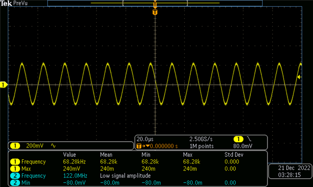
and I thought it worked pretty well,
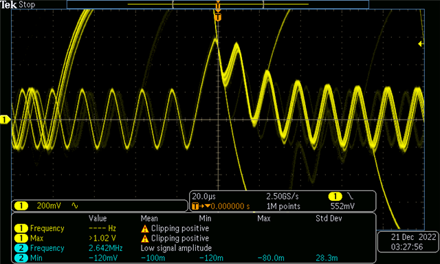
But since I request the NRF for another task, the signal has distorted like above in the middle of the signal.
Since I tried to make AM modulation/demodulation circuit with this wave, this was a huge problem for me.
I googled and found out I should approach with a timer interrupt.
So, I changed my code to the below.
int main(void)
{
    bool erase_bonds = false;
    log_init();
    timers_init();
    ble_stack_init();
    gap_params_init();
    gatt_init();
    advertising_init();
    conn_params_init();
    peer_manager_init();
  	application_timers_start();
    services_init();
    sensor_simulator_init();
    advertising_start(erase_bonds);
    csense_initialize();
	NRF_GPIO->DIRSET = 0x01 << 23;
	timerInit(50);

    while (1)
    {
//	    bsp_board_led_invert(3);
//      nrf_delay_ms(2);

        if (NRF_LOG_PROCESS() == false)
        {
            power_manage();
						NRF_LOG_FLUSH();
					__WFI();
        }
    }
}


void timerInit(uint16_t period_us) // function for timer init
{
	NRF_TIMER4->TASKS_STOP	 = 1;			// stop the timer
	NRF_TIMER4->TASKS_CLEAR  = 1;			// clear
	NRF_TIMER4->MODE		 = TIMER_MODE_MODE_Timer;	// set as timer mode
	NRF_TIMER4->BITMODE		 = TIMER_BITMODE_BITMODE_32Bit; // timer counter as 32bit
	NRF_TIMER4->PRESCALER	 = 1; //prescaler as 1
	NRF_TIMER4->CC[0]		 = (float)8000000 * ((float)period_us / 1000000.0f);
	NRF_TIMER4->INTENSET	 = 65536; // timer intrupt active
	NRF_TIMER4->SHORTS		 = 0x01; // short cut register activate
	NVIC_EnableIRQ(TIMER4_IRQn); // timer interupt function activate
	NRF_TIMER4->TASKS_START  = 1;
}
However, there were 2 problems.
One is I cannot adjust the period of the signal or duty cycle.
Even if I can adjust slightly for the pulse width, I cannot change the period of the signal.
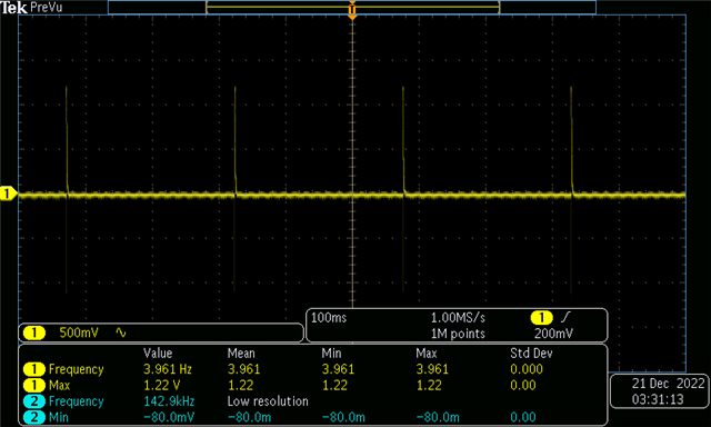
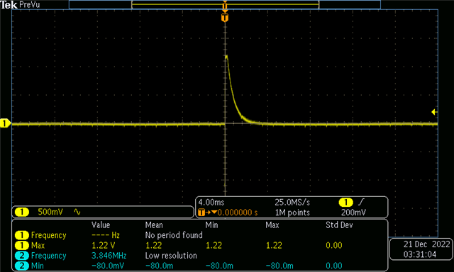
And another problem is the resolution looks really bad even though the signal was not a high frequency.
I was able to see the fall time of the pulse.
Is there any way for me so I can make a clear sinusoidal (or square) wave by using NRF52832?
What could be the problem with my code?

