PWM not working after upgrade to nrf Connect SDK 1.9.1

Since upgrading to nrf Connect SDK 1.9.1, I no longer have PWM output. No errors returned when calling pwm_pin_set_usec, yet no output.

I tried upgrading to the latest nrf Connect SDK (2.2.0), thinking that perhaps a bug was fixed, but the number of changes (include paths, etc) was too daunting.

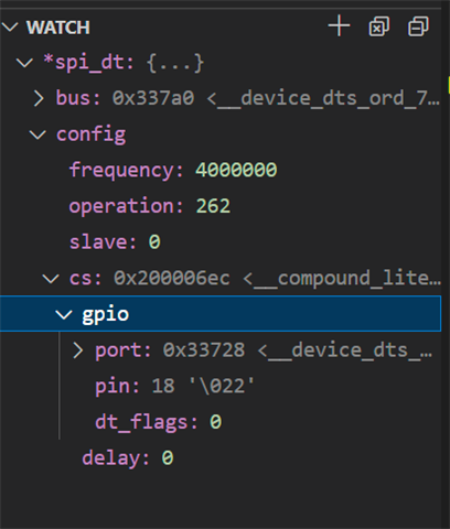
  • Some additional data. I think that my configuration of the DTS is correct. If I breakpoint in my SPI code at line 50 above, I can watch the spi_dt variable. If I set the cs-gpios to GPIO_ACTIVE_HIGH, I get the following:

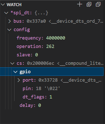
    If I set the cs_gpios to GPIO_ACTIVE_LOW, I get the following:

    So, I think that I am properly setting up the device tree, it just seems that the code that is supposed to interpret the dt_flags field is not honoring it when configuring the chip select. This is quite frustrating since I am so close to getting my device to work, but this one thing makes it completely useless.

  • Hi,

    csteaderman said:
    So, I think that I am properly setting up the device tree,

    I agree; it looks like the devicetree is

    A colleague of mine has an NCS-SPI-Master-Slave-Example.

    In this sample,  it looks like he has to get the GPIO configuration manually from the devicetree to use for his SPI functions:

    It looks like you are creating spi_cfg manually in your code posted below.
    But you set the CS pin to ACTIVE_LOW in your code manually as well, so I would think this should be enough hmm.

    So to test if ACTIVE_HIGH/ACTIVE_LOW works, I took the NCS-SPI-Master-Slave-Example sample.
    I built it for nRF Connect SDK v2.2.0 and ran it on an nRF52840DK.

    Then I change the CS Pin to LED3:

    diff --git a/nrf52840dk_nrf52840.overlay b/nrf52840dk_nrf52840.overlay
    index 84cbaaa..a3addf7 100644
    --- a/nrf52840dk_nrf52840.overlay
    +++ b/nrf52840dk_nrf52840.overlay
    @@ -41,7 +41,7 @@ my_spi_master: &spi1 {
            status = "okay";
            pinctrl-0 = <&spi1_default>;
            pinctrl-1 = <&spi1_sleep>;
    -       cs-gpios = <&gpio0 28 GPIO_ACTIVE_LOW>;
    +       cs-gpios = <&gpio0 15 GPIO_ACTIVE_LOW>;^M
            reg_my_spi_master: spi-dev-a@0 {
                    reg = <0>;
            };
    @@ -53,4 +53,4 @@ my_spi_slave: &spi2 {
            pinctrl-0 = <&spi2_default>;
            pinctrl-1 = <&spi2_sleep>;
            def-char = <0x00>;
    -};
    \ No newline at end of file
    

    I observe that LED3 is off.

    Then I change the CS pin to ACTIVE_HIGH:

    diff --git a/nrf52840dk_nrf52840.overlay b/nrf52840dk_nrf52840.overlay
    index 84cbaaa..9633808 100644
    --- a/nrf52840dk_nrf52840.overlay
    +++ b/nrf52840dk_nrf52840.overlay
    @@ -41,7 +41,7 @@ my_spi_master: &spi1 {
            status = "okay";
            pinctrl-0 = <&spi1_default>;
            pinctrl-1 = <&spi1_sleep>;
    -       cs-gpios = <&gpio0 28 GPIO_ACTIVE_LOW>;
    +       cs-gpios = <&gpio0 15 GPIO_ACTIVE_HIGH>;^M
            reg_my_spi_master: spi-dev-a@0 {
                    reg = <0>;
            };
    @@ -53,4 +53,4 @@ my_spi_slave: &spi2 {
            pinctrl-0 = <&spi2_default>;
            pinctrl-1 = <&spi2_sleep>;
            def-char = <0x00>;
    

    When I rebuild and flash this time, I observe that LED3 is on.

    From this, it looks like the CS pin ACTIVE_HIGH configuration works for this sample.

    Was this helpful?

    Regards,
    Sigurd Hellesvik

Related