Hello Nordic
I am working with nrf52840 and nrf52832 on pcbs, i want to use the nrf21540 with my pcbs to extend the strength of transmission.
I have read this data sheet : https://infocenter.nordicsemi.com/pdf/nRF21540_PS_v1.0.pdf
And saw the webinar on this page: https://www.nordicsemi.com/Products/Development-hardware/nRF21540-DB
I work with ncs1.9.2
I have some questions:
- Is there an example using the nrf21 on some other board that I can look into ?
- Can I program and work with the nrf21540 only with GPIOs ? If so, how can I configure tx power to different values ?
- When wanting to transmit, or receive, can’t we go from PD->TRX, do we have to PD->PG->TRX (that takes up to 28 microsec if i am correct ) ?
- If we need to switch from TX to RX do we need to switch TRX(TX)->PG->TRX(RX) and vice versa ? because this means transiting between receiving and transmitting taks up to 13.5 microsec, am I correct ?
I refer to this table:
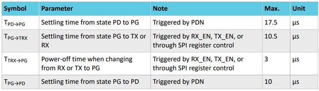
- If I want the nrf21540 to receive and transceive as the nrf52840 works, do I need to keep programming it or can it be configured somehow by UICR to certain TX power and it knows alone to pass between receiving and transmitting ?
- There are ANT1 and ANT2, why are there 2? Why can’t the be configured to work together (according to this table they can not, if i get it right)

3. What changes do I need to put in my code and where to enable the control of the nrf21 ? if i am right transmitting and receiving happens somewhere in the low level of the app in the ncs, so it seems strange to me if i need to change something there
hope to read from you soon
best regards
Ziv