
Hi,
I use SDK 17.0.2 and PCA10056 board.
I use spim3 to connect our LCD panel and I set spim3 frequency is 32MB. I can do init() LCD driver IC very well and draw some picture on our LCD panel.
But I have two questions.
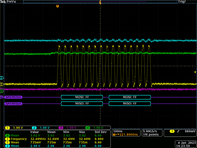
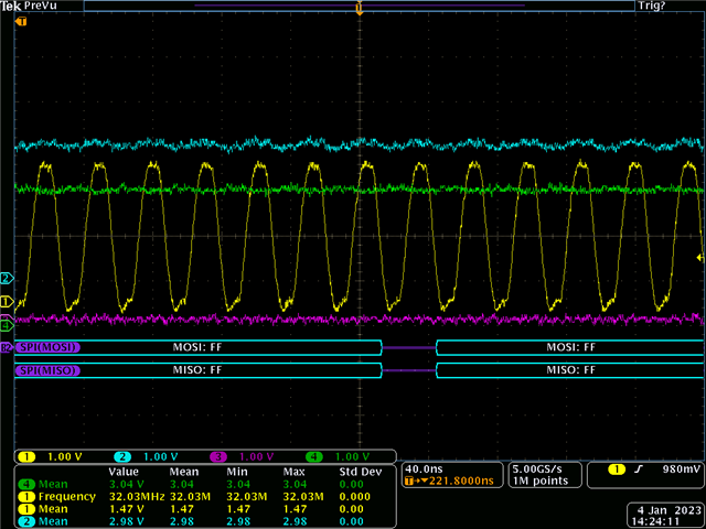
1. I have already config clock GPIO to high drive(NRF_GPIO_PIN_H0H1) and our GPIO is not low frequency GPIO(p0.24). Although we can use normal. But wave pattern of the clock doesn't look very pretty(as below). Is this normal? (Yellow line)
2. How much data can be sent at one time by DMA? Can I send 240*340*2 data size at a time?
If I cut the frame into thirds it will draw correctly
#define M2_LCD_FRAME_SIZE  240 * 320 * 2
uint8_t M2_LCD_FrameBuffer[M2_LCD_FRAME_SIZE] = {0};

void spi_lcd_ew_reflash()
{
    nrfx_spim_xfer_desc_t xfer_desc = NRFX_SPIM_XFER_TX(M2_LCD_FrameBuffer,51200);

    spi_xfer_done = false;

    APP_ERROR_CHECK(nrfx_spim_xfer(&spi, &xfer_desc, 0));
    while (spi_xfer_done == false)
    {;}

    xfer_desc.p_tx_buffer = (M2_LCD_FrameBuffer + 51200);
    xfer_desc.tx_length = 51200;
    spi_xfer_done = false;

    APP_ERROR_CHECK(nrfx_spim_xfer(&spi, &xfer_desc, 0));
    while (spi_xfer_done == false)
    {;}

    xfer_desc.p_tx_buffer = (M2_LCD_FrameBuffer + 102400);
    xfer_desc.tx_length = 51200;
    spi_xfer_done = false;

    APP_ERROR_CHECK(nrfx_spim_xfer(&spi, &xfer_desc, 0));
    while (spi_xfer_done == false)
    {;}
}
I threw the whole frame in and it doesn't seem to work
#define M2_LCD_FRAME_SIZE  240 * 320 * 2
uint8_t M2_LCD_FrameBuffer[M2_LCD_FRAME_SIZE] = {0};

void spi_lcd_ew_reflash()
{
    nrfx_spim_xfer_desc_t xfer_desc = NRFX_SPIM_XFER_TX(M2_LCD_FrameBuffer,240*320*2);

    spi_xfer_done = false;

    APP_ERROR_CHECK(nrfx_spim_xfer(&spi, &xfer_desc, 0));
    while (spi_xfer_done == false)
    {;}

}
typedef struct
{
uint8_t const * p_tx_buffer; ///< Pointer to TX buffer.
size_t tx_length; ///< TX buffer length.
uint8_t * p_rx_buffer; ///< Pointer to RX buffer.
size_t rx_length; ///< RX buffer length.
} nrfx_spim_xfer_desc_t;
So is the length limited to uint16_t? I remember size_t is uint32_t in SDK 17.
Thank you.
John.
