Hi there,
I am developing a board that contains an nRF52832 chipset using the AN043 PCB antenna design by Texas Instruments.
I have aquired a VNA from Megiq, and I am trying to figure out how to best connect the VNA to the antenna feedpoint to measure the performance of the antenna and impedance matching network.
The Megiq VNA comes with a calibration kit with UFL connectors, making it easy to calibrate the reference plane to the end of the UFL cable. However, I can't find many examples of boards that contain a footprint for a UFL connector inline with the antenna matching components, and from reading various application notes, it seems the common approach is to solder a thin coax cable directly to the start of the antenna matching network (making sure to disconnect the radio matching network).
I cannot find a detailed explaination in any application notes related to antenna tuning how to properly calibrate the VNA reference plane when using a bare coax cable. Since the end of the cable will not have a UFL connector, I would not be able to use the calibration kit that comes with the VNA.
What is the most reliable approach to calibrate the VNA when using a bare coax cable?
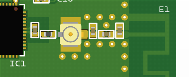
Alternatively, I could include a UFL connector footprint on the PCB infront of the antenna matching components (similar to one of the nRF dev kits), which would be populated during development but left unpopulated during production. This would make it much easier to calibrate the VNA using the included UFL calibration kit and reliable connect the VNA to the PCB.
Are there any problems with this approach?