Understanding processor halt when SWDIO/SWCLK are pulled high/low respectively

Hello,

I am working on a custom board which has a multiplexer connected to route two output pins to either UART RX/TX lines or SWDIO/SWCLK.

The multiplexer is controlled by the nRF application, and selecting either mode works as expected (can enable UART comms and send messages at 1MBaud, or communicate over SWD when this mode is selected and attach a debugger and program).
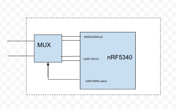
I noticed an issue, however, that connecting a UART device externally while routed to the SWDIO/SWCLK pins on the nRF can cause the processor to halt, and I would like to understand what is happening. Specifically, I was able to isolate the issue down to the following error case, and was able to reproduce.

1. If SWCLK is driven high (1.8V)

2. And then SWDIO is temporarily driven low (short to ground briefly, or falling edge on SWDIO)

The processor halts, and does not resume operation, until drive on SWCLK is removed (internal pull-down on nRF5340 brings SWDIO low again).

On our custom board, during startup, if the UART lines are connected via the mux, an external pull-on UART RX causes SWCLK to pull high, and then a falling edge on UART TX (data transmission over the UART interface) causes the device to halt until the uart pull up is disconnected.

Can you please help me understand why this is happening? I think that the problem can be resolved by removing the pull up on UART RX (this is not ideal from our application because then that UART line is in a non-deterministic state and can lead to framing errors when the device is not connected, but this is better than having the nRF5340 stop responding.

Mostly I want to understand the failure mode to make sure that my solution works in all cases.

Thanks in advance!

  • Hi,


    Do I understand the scenario correct that you're sending UART data into the SWD pins?

    If yes, then unwanted behavior can happen, as SWD is also a serialized bus.

    Please see the SW-DP specification for more information: https://developer.arm.com/documentation/ddi0413/c/debug-access-port/sw-dp/protocol-description


    Kind regards,

    Håkon

  • Hi Håkon, you're correct that I'm looking at the case where UART TX data could be muxed to a SWD line, but only one of the lines has data on it (UART TX) and the other line has a pull up (the UART RX line).

    I looked through the SWD spec that you linked, but it did not explain the behavior that I saw. Specifically, pulling SWCLK high and then temporarily shorting SWDIO low does not seem to be valid according to the SWD protocol, so I'm not sure why the processor would halt. 

    In our design, there is no way to avoid that UART TX data could potentially end up on one of the lines, but the workaround we have is to not enable the pull-up resistor on the UART RX line, (so that SWCLK does not end up pulled high), but we need to make sure this will resolve the issue we were seeing in all situations.

    Is there any documentation about the internal SWD debug handling in the nRF? The provided documentation does not seem to explain why this resulted in the processor being halted.

    Thanks!

    Nick

  • Hi,

    nwl_at_whisper said:
    Is there any documentation about the internal SWD debug handling in the nRF? The provided documentation does not seem to explain why this resulted in the processor being halted.

    We implement the standard component from ARM. The specification is available from ARMs website:

    https://developer.arm.com/documentation/ihi0031/latest

    The first chapter in the previous link (although it mentions cortex m1, it applies to the whole cortex m family) can explain the behavior that you're seeing:

    The serial interface to the SW-DP must use a connection sequence, to ensure that hot-plugging the serial connection does not result in unintentional transfers. 
    The connection sequence ensures that the SW-DP is synchronized correctly to the header that is used to signal a connection. 
    It consists of a sequence of 50 clock cycles with data = 1, that is, with the serial data signal asserted HIGH by the debugger.
    
    This connection sequence is also used as a line reset sequence, see Protocol Error responses on page 5-13. 
    The protocol requires that any run of 50 consecutive 1s on the data input is detected as a line reset, regardless of the state of the protocol.


    Have you scoped the SWD pins to see how these signals behave when you get into this unwanted situation?


    Kind regards,

    Håkon

Related