Hi,
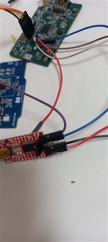
1. Here I am using the nrf52840 in my customized board, in parallel I have nrf52840 dev board. In My custom Onboard debugger is not available so I am using SWD to load the program from NRF52840 DK board to Custom Board (NRF52840).
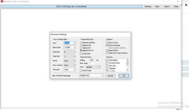
2. I am loading TWI Scanner Example program to my custom board, from that nothing is displayed on terminal, But If I am flashing same TWI scanner example to Dev boards its working and its displaying like TWI Scanner Started But in my custom board nothing is displayed.
3. I have mention I2C pin as P0.06 & P0.07, and also I have mention UART in my custom board as P1.11(TX), P1.12(RX), P1.10(CTS), P0.30(RTS).
My doubt why log is not displaying anything in my custom board. and one more doubt also whether I have to mention custom board UART pins in TWI Scanner Example??
I have raised this questions in my previous thread, there is no reply that's why I posed this thread. Please anyone help me on this. I am waiting for your quick response...
Thanks in advance.