4 second current spikes during sleep

Hello All,

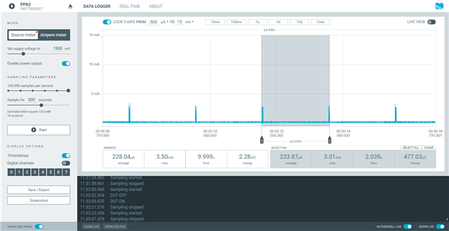
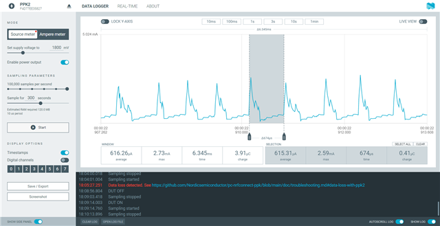
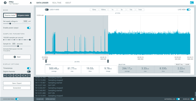
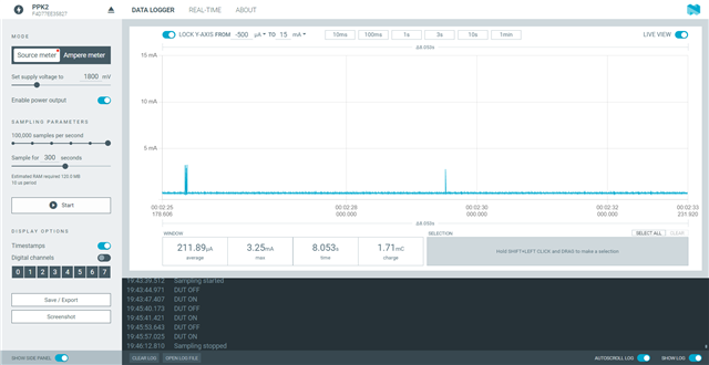
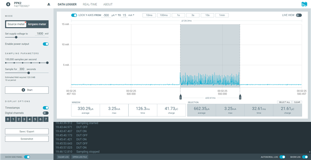
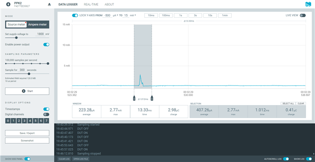
I am getting these ~3.5mA current spikes very 4 seconds and I can't seem to figure what the cause of them is. some of the spikes have a single spike/pulse while other have multiple. please see the attached images. I have commented out everything except the while in the main function and no difference. I have also commented out the enabling of the DCDC and still the same issue. any help would be greatly appreciate. I have a feeling its in the project config setting but tried commenting out what I thought may be the cause but no change either. 

I am using a custom board with 52833 and nRF Connect SDK 2.0.0. the board does have other ICs(hall sensors) but I measured their consumption and had no spikes.

while (1) {
		//k_sleep(K_SECONDS(1));
		//k_msleep(500);
		
		__WFE();
}

my project config file


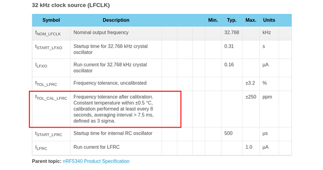
#CONFIG_DK_LIBRARY=y

# Config logger
CONFIG_LOG=n
CONFIG_USE_SEGGER_RTT=n
CONFIG_LOG_BACKEND_RTT=n
CONFIG_LOG_BACKEND_UART=n
CONFIG_LOG_DEFAULT_LEVEL=3
CONFIG_DEBUG_OPTIMIZATIONS=n
# CONFIG_LOG_MODE_IMMEDIATE=n


CONFIG_SERIAL=n
CONFIG_CONSOLE=n
CONFIG_UART_CONSOLE=n

# Config Bluetooth
CONFIG_BT=y
##CONFIG_BT_DEBUG_LOG=y
##CONFIG_BT_SMP=y
CONFIG_BT_PERIPHERAL=y
CONFIG_BT_DIS=y
CONFIG_BT_DIS_PNP=n
# CONFIG_BT_BAS=y
# CONFIG_BT_HRS=y
CONFIG_BT_DEVICE_NAME="XXX Sensor"
CONFIG_BT_DEVICE_APPEARANCE=0
#CONFIG_BT_DEVICE_APPEARANCE=833
CONFIG_BT_LL_SOFTDEVICE=y
CONFIG_BT_MAX_CONN=1
CONFIG_BT_GAP_PERIPHERAL_PREF_PARAMS=y
CONFIG_BT_PERIPHERAL_PREF_MIN_INT=40
CONFIG_BT_PERIPHERAL_PREF_MAX_INT=45

CONFIG_BT_BUF_ACL_RX_SIZE=251
CONFIG_BT_BUF_ACL_TX_SIZE=251
CONFIG_BT_L2CAP_TX_MTU=247
CONFIG_BT_CTLR_DATA_LENGTH_MAX=251
CONFIG_BT_BUF_ACL_TX_COUNT=10


# CONFIG_CLOCK_CONTROL_NRF_FORCE_ALT=y wh
CONFIG_CLOCK_CONTROL_NRF=y
CONFIG_CLOCK_CONTROL_NRF_K32SRC_RC=y
CONFIG_CLOCK_CONTROL_NRF_K32SRC_XTAL=n
# CONFIG_CLOCK_CONTROL_NRF_K32SRC_XTAL is not set
# CONFIG_CLOCK_CONTROL_NRF_K32SRC_SYNTH is not set
# CONFIG_CLOCK_CONTROL_NRF_K32SRC_EXT_LOW_SWING is not set
# CONFIG_CLOCK_CONTROL_NRF_K32SRC_EXT_FULL_SWING is not set
CONFIG_CLOCK_CONTROL_NRF_K32SRC_RC_CALIBRATION=y
CONFIG_CLOCK_CONTROL_NRF_CALIBRATION_LF_ALWAYS_ON=y
CONFIG_CLOCK_CONTROL_NRF_K32SRC_500PPM=y
CONFIG_GPIO_AS_PINRESET=n


CONFIG_GPIO=y
CONFIG_GPIO_NRFX=y
CONFIG_NRFX_GPIOTE=y
CONFIG_SPI=y

#CONFIG_ASSERT=y

#CONFIG_NRFX_PRS_BOX_2=y

# CONFIG_NRFX_TIMER0=y
CONFIG_NRFX_TIMER1=y
CONFIG_NRFX_TIMER2=y
CONFIG_NRFX_TIMER3=y
CONFIG_NRFX_TIMER4=y
CONFIG_NRFX_PPI=y
CONFIG_NRFX_GPIOTE_NUM_OF_EVT_HANDLERS=2
CONFIG_NRFX_SPIM0=y
CONFIG_NRFX_SPIM1=y
CONFIG_COUNTER=y
#CONFIG_COUNTER_TIMER1=y


CONFIG_NRFX_RTC2=y
CONFIG_NRFX_POWER=y


##CONFIG_PM=y
# Required to disable default behavior of deep sleep on timeout
##CONFIG_PM_DEVICE=y
#CONFIG_GPIO=y
# Optional select RAM retention (nRF52 only)
#CONFIG_APP_RETENTION=y


  • Hello, 

    Please set CONFIG_CLOCK_CONTROL_NRF_CALIBRATION_MAX_SKIP=0 and then try to adjust the  CONFIG_CLOCK_CONTROL_NRF_CALIBRATION_PERIOD setting to see if it affects the interval of your current spike. The 2nd screenshot looks could be showing the clock calibration event (The 32K RC oscillator is calibrated periodically against the HF crystal oscillator). 

    Best regards,

    Vidar

  • Hi Vidar,

    That seems to be it. I set the following

    CONFIG_CLOCK_CONTROL_NRF_CALIBRATION_MAX_SKIP=0
    CONFIG_CLOCK_CONTROL_NRF_CALIBRATION_PERIOD=2000
    and period did change accordingly. please see plot.
    So with that said, I have few questions. 
    1) will an external 32kHz crystal use less power? or
    2) Since we know our device will be operating in a fairly temp controlled environment, what do you think would be wise settings to minimize power consumption but not get some egregious clock drift? 
    for example, do the cal every x number of deg change if possible. what do you think that x should be
    or do it every x seconds(what do you think that x should be)
    your help is greatly appreciated.
    Regards,
    Wael
  • Hi Wael,

    Wael said:
    1) will an external 32kHz crystal use less power? or

    The internal RC oscillator will lead to a slightly higher average current for the following reasons: 

    1. The Bluetooth controller will need to increase its RADIO RX listening windows to compensate for the additional clock drift compared to the LF crystal oscillator.

    2. Requires periodic calibration,

    3. RC oscillator has a higher run current.

    You can estimate how much impact the clock source will have on your application (in terms of average power consumption) by using our online power profiler here:   

       Online Power Profiler for Bluetooth LE   

    Wael said:
    2) Since we know our device will be operating in a fairly temp controlled environment, what do you think would be wise settings to minimize power consumption but not get some egregious clock drift? 
    for example, do the cal every x number of deg change if possible. what do you think that x should be
    or do it every x seconds(what do you think that x should be)

    I think you can extend the interval to 8 seconds. From the PS:

    Regards,

    Vidar

  • Hi Vidar,

    Thank you for your reply. this makes complete sense. I now have another power consumption issue. My app does the following using PPI, SPIM, GPIOTE, and timers

    the PPI configuration is as follow:

    1) Upon receiving a GPIOTE trigger from an IMU(every 8.3 seconds), read its data (this is operating on a dedicated spi bus, SPIM0)

    2) write a dummy read command to an FRAM IC to wake it up from hibernate state (SPIM1 bus)

    3) trigger timer for 8ms from the start of the FRAM SPIM transaction(step 2)(period for FRAM to become stable from hibernate state)

    4) write the WREN(write enable) command to the FRAM upon completion of the 8ms timer

    5) write the (write command, address, data) to the FRAM

    6) write the hibernate command to the FRAM

    the multiple writes(aside from step 5) can NOT be combined as the bus CS pin needs to be toggled for the memory chip to accept the commands.

    to do this, I used 2 spi buses and 4 timers(one timer mode for the 8ms delay and 4 counters)

    In sum, my code works exactly as described and verified using oscilloscope. 

    my issue is after the first PPI transaction is triggered, something is consuming power and/or is staying on. has between 650 and 850us periods. please see the first plot below. Note: approx. 200uA of the 600uA is from my external peripherals on the board. 

    the 2nd plot shows this issue does not exist prior to the first PPI transaction. 

    I do not think its a timer issue. I have read that the EasyDMA does consume ~1.5mA but that should only be during transmission. and the frequency of these pulses do not correlate to any SPI transaction. I have not been able to isolate the cause of this and your time and effort would be greatly appreciated.

    Regards,

    Wael

  • Hi Wael,

    Could you please try to use a GPIOTE PORT event to detect when the IMU's interrupt line is asserted and trigger the SPI task from your app instead of using PPI? You should see a lower floor current when using GPIOTE PORT event compared to when you have IN events enabled.

    [153] GPIOTE: GPIOTE with low-power latency setting does not register IN events in System ON IDLE

    Regards,

    Vidar

Related