Using NRF Connect RSSI viewer with radio test sample

Hi

I am working with the radio test sample. I am using the RSSi viewer for testing as detailed here. I am guessing that I need two development kits here - one with the sample flashed (A) and another one that is connected to the PC with RSSI viewer (B). The RSSI application programs the device B. This is my understanding about the setup. However, even without my device A powered down, I can see some activity in the RSSI viewer. I have no other bluetooth devices in the vicinity. Hoping to see a change in the observed pattern, I turned the device A on and used the following commands

output_power pos4dBm

start_tx_modulated_carrier

However, I could not see any change in the RSSI viewer. Is there anything that I am doing wrong ?

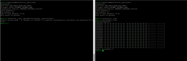
Also, I tried using the testing method using another DK as described here. This time, I could see the received packets but I cannot see any changes when I use print_rx on B when i change the output power of device A. How do I analyze the pattern ?

Thank you

Parents
  • Hey Midhunjac,

    However, even without my device A powered down, I can see some activity in the RSSI viewer. I have no other bluetooth devices in the vicinity.

    RSSI samples any received RF waves in a given channel, no matter the source, it's just an analog sample of the energy present in the input stage of the receiver. This means that the RSSI Viewer will sample a lot of WIFI noise due to the high transmission power and wide frequency bands of WIFI devices.

    How much noise(RSSI) is present in the channel that you are using when the Radio Test transmitter is not transmitting?

    However, I could not see any change in the RSSI viewer. Is there anything that I am doing wrong ?

    I'm not quite sure. My advice is to set the RSSI Viewer app to scan only on the channel that you are using (default channel is 0), and place the Radio Test transmitter and RSSI Viewer receiver devices as close to each other as possible. The RSSI should be closer to -50/-60dBm on 0dBm TX power when the two devices are ~5cm apart. It's been a while since I've measured RSSI myself so my numbers might be a bit off.

    You can also use channel 2 as it should contain less BLE noise from the Advertising channel 0 @2402MHz and still be as far away from the default wifi channels as possible.

    How far apart are the two devices?

    Are any of the devices custom designs or are they all nRF52xx DK's?

    BR,
    Håkon Holdhus

  • Hi,

    Thank you for the reply. I think I get what you are saying about the RSSI viewer application. I will try it out and then post the updates.

    How far apart are the two devices?

    10cms maybe. no more than that.

    Are any of the devices custom designs or are they all nRF52xx DK's?

    I have one on DK - nrf52832 for testing. And a custom board with nrf52840.

    Also, as I mentioned before, I tried radio sample with the method described here. I could see that the receiver did receive something but it is different each time for the same test case. Is that how it is supposed to be ?

    I would like to learn how to analyze these received patterns. Can you guide me to a starter's guide or documentation please?

    Thank you

  • Midhunjac said:
    Also, as I mentioned before, I tried radio sample with the method described here. I could see that the receiver did receive something but it is different each time for the same test case. Is that how it is supposed to be ?

    Hmm, I would expect the received data to be random only if you set transmit_pattern to pattern_random.

    There's no guide in interpreting the RAM content (I assume addresses are offset by ram_start), the radio test sample is pretty basic with regards to features. If there is an issue it's either in the shell-configuration of the transmitter and receiver, or there's a HW RF issue with one of the boards. That's at least where we should be looking.

    What are you using this test set-up to test for? Are you validating the TX output power of your custom board?

    Have you had a design review of your board yet?

    Have you tuned the antenna?

Reply
  • Midhunjac said:
    Also, as I mentioned before, I tried radio sample with the method described here. I could see that the receiver did receive something but it is different each time for the same test case. Is that how it is supposed to be ?

    Hmm, I would expect the received data to be random only if you set transmit_pattern to pattern_random.

    There's no guide in interpreting the RAM content (I assume addresses are offset by ram_start), the radio test sample is pretty basic with regards to features. If there is an issue it's either in the shell-configuration of the transmitter and receiver, or there's a HW RF issue with one of the boards. That's at least where we should be looking.

    What are you using this test set-up to test for? Are you validating the TX output power of your custom board?

    Have you had a design review of your board yet?

    Have you tuned the antenna?

Children
  • Have you had a design review of your board yet?

    Have you tuned the antenna?

    The design review is not done yet. I just wanted to get a hold of the test procedure with the DK ahead of the actual test. Hence the radio test sample. I am new to this thing and still learning. I appreciate your effort in helping out. I will get back after the tests with the DK.

    Thank you

  • Also, I am following this method for now to test and from what I understand, when transmit_pattern is 11110000, I should get F0 and if it is set to 11001100 I should get CC at the receiver side. Am I right here ?

    If that is the case, am I right in assuming that there is no way by which I can make sure that the changes that I make to the output power using output_power command in transmit side actually has an effect ?

  • Yes, that is was I expect as well. I checked the shell commands for the sample, it only accepts the values pattern_random, pattern_11110000, and pattern_11001100 as values for transmit_pattern.

    Can you share a transcript/log of the shell sessions for the transmitter and receiver? I just wanna double-check that it is set-up properly.

    As for a HW design review I suggest you open a new 'private' ticket and ask for a HW review. You can link to this ticket and it'll be delegated to me if I'm available.
    We will need schematics and layout files, as well as a BOM for the crystals and passive components in the RF domain.

  • Hi,

    Here is the log. I believe it is working as it should be. The only problem I have here now is that I have no way of verifying the output_power set by the transmitter. Is there some way i can verify that too ?

    Thanks

  • Midhunjac said:
    The only problem I have here now is that I have no way of verifying the output_power set by the transmitter. Is there some way i can verify that too ?

    I would start by calling parameters_print on the transmitter, after you've set the new TX Power value, just to verify that the radio test application believes it's in the correct state.

    Then I would use the RSSI viewer on a third device (nRF52 series DK ), and set it to scan on channel 0 ( == Start Channel). If you place the transmitter right next to the RSSI measuring device (third device, dk) it should be the largest signal 99% of the time and that should enable you to measure a difference of ~4dBm, given that you do not change the positision of any of the devices between measurements.

    Note that the RSSI cannot give you the absolute value of the transmit power, for that you need a conducted measurement from a properly calibrated signal analyzer rated for at least 2.5GHz.

    We can do that for you as part of our pre-certification scan and antenna tuning service if you do not have the means to do so yourself.

Related