Direction finding, antenna switching AoA Rx (question)

Hi,

I had been read the white paper and it comes to antenna switching patterns. White Paper its tells me:

When the last switch pattern is reached and IQ sampling continues, the switch pattern loops back to the one used in the first SWITCH slot. The following diagram shows five antenna patterns that have been loaded.

With a linear array of 4 antennae and their gpio pattern 0..3
my understanding is:

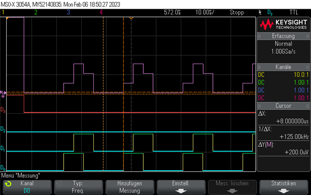
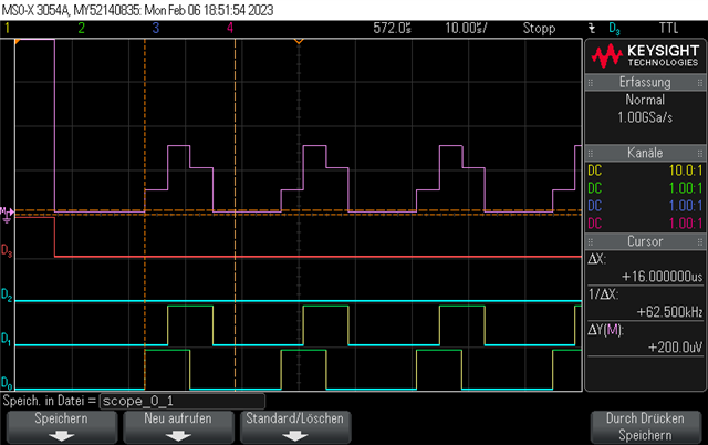
  • that the gpio is set to the pattern[0] for guard and reference (4+8us)
  • and then loop over gpio pattern 1..3 for the CTE switch/slot period.

Please let me know if I'm right.

Thanks
Chris

  • Hello Chris,

    It is set to the first pattern in the data section of the packet, then the second pattern is set to the reference period. You'll then probably use the third pattern in the first switch slot, and the rotation of your patterns then continues back to the third one after finishing.

    Note that using a certain pattern doesn't imply using a certain antenna. Given the 4 antennas in your array you can still have eg. 10 patterns in rotation, with multiple patterns being the same and pointing back to the same antenna.

    If you are to make a Bluetooth compliant solution then the pattern should always rotate through the reference antenna, this can be done by having the reference antenna (pattern entry 2) as the last entry in the pattern table. It will then be part of the "looped" pattern.

    Regards,

    Elfving

  • Hi Elfving,

    I thank you very much for your reply.

    The zephyr code example is a bit miss leading in reading, but with your explanation it makes sense to me now.

    so I will make my mapping like this:

    • pattern idx=0 -> antenna 1 (data section)
    • pattern idx=1 -> antenna 1  (guard & reference) 
    • pattern idx=2 -> antenna 2 (first slot .. repeat )
    • pattern idx=3 -> antenna 3 (second slot ..)
    • pattern idx=4 -> antenna 4 (third slot ..)
    • pattern idx=5 -> antenna 1 (fourth slot ..)  for Bluetooth compliant

    you mentioned 10 patterns for rotation which make sense to use all 30 iq-samples after the 8 iq-samples of the
    reference period (8us). But I think its less tricky for a syhmetric matrix to use 28 iq-samples only and leave 2 iq-samples untouched and use a 4 x 7 matrix which is then average per row and do the SVD calculation.

    I have already ported the zsclib module to deal with the complex data. Hope to see the first AoA soon.

    Cheers
     Chris

  • Hi Elfving,

    I implement what I wrote and can see on my digital oscilloscope the
    chip-select (D3) and the switching D0..2 needed for the SP4T chip.

    But with every loop back to pattern#2 8us pause measure before repeat the switching. 

    where the switching is with 16us ok

    This might be a configuration issue?

    Chris

  • Maybe so. It seems to be in the final antenna pattern for 3 slots.

    Could you show me how you've setup your antenna pattern?

    Regards,

    Elfving

  • Hi,

    I open a private ticket on this case because it's 

    Not related to the original topic.

    You had helped me with your reply and I'm happy with the outcome.

    Cheers

    Chris

Related