Using debugger on nRF52840DK to flash code to another nRF52840DK

Hi!

I'm a student working on my master thesis with almost no experience to the nRF52series.

I initially want to flash code though a nRF52840DK using the onboard debugger to a custom board with a nRF52840.

I'm not sure if there is hardware/design faults on the board or that my setup from the nRF52840DK to my board is wrong. I used the programmer tool from "nRF Connect for Desktop". I assumed that when connected to the nRF52840DK my nRF52840 (on the custom board) would appear when choosing devices. That did not happen.

The connection that has been made:

  • µUSB to the nRF52840DK
  • Cable from Debugout on the nRF52840DK to Debugin on my custom board.
  • My custom board is power through an external power supply. 

Because I was unsure of design faults on my custom board I tried setting up two nRF52840DK to ensure that my debug setup was correct.

Connections that has been made with two nRF52840DK:

  • µUSB to nRF52840DK(1)
  • Cable from debug out on nRF52840DK(1) to debug in on nRF52840DK(2)
  • µUSB to nRF52840DK(2) connected from another pc than the nRF52840DK(1)

For both DK:

  • SW8 is switched to ON
  • SW6 is switched to DEFAULT
  • SW9 is switched to VDD

The cable I have used between the debugout and debug in are a  two 10pin flat cable that are connected together (not reversed) 

Is my setup wrong? How can I program an external board or another nRF52840DK by using the onboard debugger on a separate nRF52840DK?

  • Hello,

    It is not easy to say why it is not working out of the box, but we can have a look into some possible reasons.

    What voltage is your custom board running on? 

    What is the version of the DK you are using? What does it say on the white sticker on the second line? It should say something like:
    PCA10056
    X.Y.Z
    ...

    What is X, Y and Z?

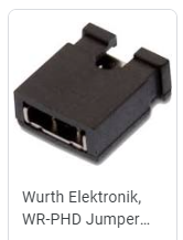
    I understand what you are trying to do with the different computers, but it is important that the two boards have common ground (and the same VDD). If you want to make sure that you are not programming the nRF on the DK, you can cut SB40 with a sharp utility knife. Note that this requires you to short the connector on P22 to use the nRF52840 on the DK later. You can either use a jumper cable, or a jumper shunt like this:

    Because I was unsure of design faults on my custom board I tried setting up two nRF52840DK to ensure that my debug setup was correct.

    Did that work or not?

    For both DK:

    • SW8 is switched to ON
    • SW6 is switched to DEFAULT
    • SW9 is switched to VDD

    That looks good. 

    For the debug in port on your custom board, can you upload some schematics saying how these pins are connected?

    The cable I have used between the debugout and debug in are a  two 10pin flat cable that are connected together (not reversed) 

    Did you use two cables? or did you mean "two row 10 pin"?

    Best regards,

    Edvin

  • Hi Thank you for your answer!

    I used two cables and all 10 pins where connected at first but I read somewhere here that you only needed 4 pins to connect the debugger to another board. I guess there was some ground issues with my setup with the cables and everything worked when I connected all 10 and used them with the different "settings" on the board. 

    I also uninstalled nrf connect and only tried flashing code onto one of the nRF52840DK with another nRF52840DK. Switched the SW6 on the DK that I wanted to program from nRF ONLY to DEFAULT and I could see that the LED I wanted to blink was blinking :)

    The settings I had for the DK I wanted to program:

    - SW8 : ON
    - SW6: nRF ONLY
    - SW9: VDD

    The settings I had for the DK where I used the onboard debugger remained the same as I wrote above. 

    Since the debug setup was good I just unpluged the 10pin cable from the DK(the one I wanted to program) onto my custom board and everything went great :D

    Everything worked and the end!

  • Glad to hear that it worked out!

    Most of these cases, there is an issue with GND detect and VDD Detect. The 10 pin cable (or the 4 wire approach) doesn't power the external board, but parts of the pins are used to detect that there is a board attached to the debug out port (GND and VDD Detect). So as long as GND detect and VDD Detect are properly connected, both boards have the same GND and VDD, then it works (most of the times) Slight smile

    Have a nice weekend!

    Best regards,

    Edvin

Related