Beware that this post is related to an SDK in maintenance mode
More Info: Consider nRF Connect SDK for new designs

is there a limit of the sampling rate to get analog signal?

Hello, I am trying to capture the analog signal from two pins.

From one channel, I could get a signal with up to a 2kHz sampling rate.

However, the problem is, I couldn't see the clean signal if I added one more channel.
The sampling rate that I can make from 2 channels was about 50~100Hz.

If I make a higher sampling rate, I can see the ruined signal.
So from the 2-channel recording, when I set the sampling rate as 50Hz and see the data after recording, the frequency looks fine (not for the shape of the signal but frequency looks fit).

However, if I set the sampling rate as 500hz, 1khz, and 2khz, I should set the sampling rate as around 200Hz on Matlab when I recover the signal to see the frequency correctly.

What I am guessing here is since recording with a specific sampling rate is essentially dividing the clock with a certain ratio, this could result from a mismatch of the timing of the signals being recorded. This leads to the loss or corruption of some parts of the signals, causing poor signal integrity.
So issue with the poor signal integrity that I am observing might be due to the timing of the shifting analog input pins when recording signals from multiple channels.

Do you think this makes sense?

Is there any idea to fix my situation?

This is the main code that I used to record the signal with one analog channel.

Fullscreen
1
2
3
4
5
6
7
8
9
10
11
12
13
14
15
16
17
18
19
20
21
int main(void)
{
// Start clock for accurate frequencies
NRF_CLOCK->TASKS_HFCLKSTART = 1;
while(NRF_CLOCK->EVENTS_HFCLKSTARTED == 0)
;
//outpin_toggling_sample();
bool erase_bonds = false;
// Initialize.
log_init();
timers_init();
//buttons_leds_init(&erase_bonds);
ble_stack_init();
gap_params_init();
gatt_init();
advertising_init();
conn_params_init();
peer_manager_init();
XXXXXXXXXXXXXXXXXXXXXXXXXXXXXXXXXXXXXXXXXXXXXXXXXX

and other codes that handle recording and Bluetooth communication or extra setting

Fullscreen
1
2
3
4
5
6
7
8
9
10
11
12
13
14
15
16
17
18
19
20
21
#define DEVICE_NAME "name" /**< Name of device. Will be included in the advertising data. */
#define MANUFACTURER_NAME "NordicSemiconductor" /**< Manufacturer. Will be passed to Device Information Service. */
#define APP_ADV_INTERVAL 160
#define APP_ADV_TIMEOUT_IN_SECONDS 180
#define CONN_CFG_TAG 1 /**< A tag that refers to the BLE stack configuration we set with @ref sd_ble_cfg_set.
Default tag is @ref BLE_CONN_CFG_TAG_DEFAULT. */
/* Time between RTC interrupts. */
#define ADC_TIMER_TICKS_TIMEOUT APP_TIMER_TICKS(0.5) // 1=1ms set the sampling rate
#define HRS_BUFFER_LEN 150 // 75 100 154
#define HEART_RATE_MEAS_INTERVAL APP_TIMER_TICKS(1500) // 1=1ms 7.5 19.25 /**< Heart rate measurement interval (ticks). */
//#define OUTPUT_PIN_INTERVAL APP_TIMER_TICKS(500) // 1.35ms 370Hz 0.5 1kHz /**< P0.18 interval 370Hz signal (ticks). */
#define SENSOR_CONTACT_DETECTED_INTERVAL APP_TIMER_TICKS(10) /**< Sensor Contact Detected toggle interval (ticks). */
#define MIN_CONN_INTERVAL MSEC_TO_UNITS(320, UNIT_1_25_MS) /**< Minimum acceptable connection interval (0.4 seconds). */
#define MAX_CONN_INTERVAL MSEC_TO_UNITS(520, UNIT_1_25_MS) /**< Maximum acceptable connection interval (0.65 second). */
#define SLAVE_LATENCY 0 /**< Slave latency. */
#define CONN_SUP_TIMEOUT MSEC_TO_UNITS(10000, UNIT_10_MS) /**< Connection supervisory timeout (10 seconds). */ \
#define FIRST_CONN_PARAMS_UPDATE_DELAY APP_TIMER_TICKS(1000) /**< Time from initiating event (connect or start of notification)
to first time sd_ble_gap_conn_param_update is called (5 seconds). */
XXXXXXXXXXXXXXXXXXXXXXXXXXXXXXXXXXXXXXXXXXXXXXXXXX

and the code that I changed to make 2 channel recording

Fullscreen
1
2
3
4
5
6
7
8
9
10
11
12
13
14
15
16
17
18
19
20
21
static int AIN_INX = 0;
#define AIN_1 0 // P0.03/AIN 1
#define AIN_3 2 // P0.04/AIN 2 for Input value
#define PAD_1_MASK (1UL << AIN_1)
#define PAD_2_MASK (1UL << AIN_3)
#define PAD_ID_0 0
#define PAD_ID_1 1
#define UART_TX_BUF_SIZE 512 /**< UART TX buffer size. */
#define UART_RX_BUF_SIZE 1 /**< UART RX buffer size. */
volatile uint32_t threshold_value_pad1 = 3000;
volatile uint32_t threshold_value_pad2 = 3000;
#define ADC_TIMER_TICKS_TIMEOUT APP_TIMER_TICKS(1) // decide sampling rate
#define HRS_BUFFER_LEN 150
uint16_t InputVal1_buf[HRS_BUFFER_LEN];
XXXXXXXXXXXXXXXXXXXXXXXXXXXXXXXXXXXXXXXXXXXXXXXXXX

Do you think there is any line that has to be fixed or a suggestion so that I can make 2 channel recording with a 1kHz sampling rate?

The image of the channel recorded signal is below (they suppose to be s perfect sine wave)

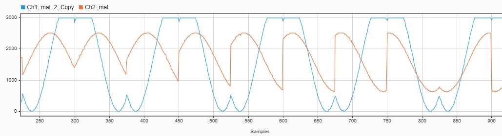
Please let me know if there is something else I can provide to fix this...

Or there is any codes or samples that I can make as references.