Mesh Optimization / TTL, Relay Nodes, Difficult Floorplan

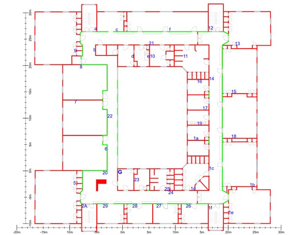
I'm looking for some feedback. We are running a pilot with 38 nodes in a Bluetooth Mesh. The building is a roughly square layout with 4 main corridors following the outside of the square. The center of the square is exterior to the building. The gateway (denoted by "G") is in the bottom left corner. The sensor locations are shown by ID. I've added a rough rule for scale -- the total footprint is roughly 40m x 45m. We get a range of ~10m per node in normal indoor conditions. We are using the nRF SDK 17.0.2 and nRF5 SDK for mesh. We have not yet made the switch to Zephyr.

As you can see from the layout, some nodes (like those in the corridor at the top of the drawing, C/F/12/13) will require relaying multiple times.

Questions:

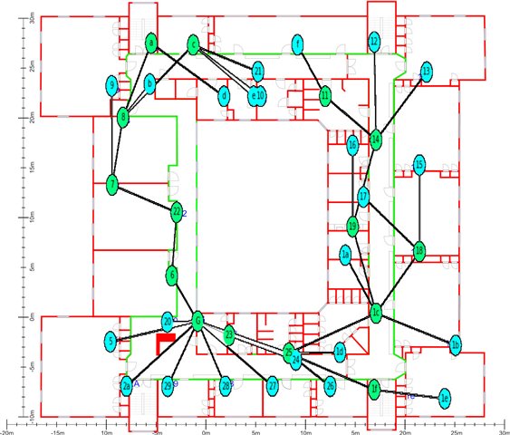
1/ Because of the physical layout, we are struggling a bit with which nodes should be relays. Obviously within close groups like d/e/10/21 only one might need to be a relay. However, for nodes separated by greater distance like 6/7/8 or 15/18/1b, presumably all would need to be relays? What rule of thumb would you use to determine which should be nodes and which should not?

2/ I understand that there is no formal message routing. Clearly there are some nodes we can set with TTL=1 or TTL=2, but it is unclear to me how to balance a high degree of certainty that a message will arrive with the need to optimize the network. Nodes that are far from the gateway, like F/12/13 could use as few as 7 hops, or as many as 20 depending on path and number of relays. My current thought is to have 3 or 4 groups, each with different TTL based on approximate/guessed number of hops, but I'm not sure that's the best way to go. This comes down to the same question as above: what rule of thumb can we use to optimize TTL? 

3/ One of the greatest advantages of Bluetooth Mesh appeared to be the lack of configuration needed by an end user once a device is provisioned. However, optimizing TTL and relays is clearly site dependent.
  -- Has anyone been able to automate this optimization process so minimal manual configuration is needed by the end user?
  -- Are there any available resources to help with automating this type of optimization?

All suggestions are most welcome.

  • So I've received multiple notifications from Nordic that an engineer has been assigned, but no answers? It's been a week. Could someone from Nordic please respond?

  • Hi,

    I am sorry for the delays.

    What rule of thumb would you use to determine which should be nodes and which should not?

    Assuming that by "nodes" you mean "relay nodes." I would try to get all nodes (including relay nodes) within range of at least 2 (other) relay nodes.

    This comes down to the same question as above: what rule of thumb can we use to optimize TTL?

    From experience we know that it is best to set the TTL slightly higher than theoretically needed, since the shortest path is not always chosen, in terms of number of hops. The main use of TTL is to prevent messages from propagating through the whole network, when the destination is known to be in closer proximity than the farthest away node. If spreading to the whole network is fine, then it is better to just set it to the highest value. You can do this if you expect the total network traffic not to cause congestion, even if all messages are relayed to every node. In a setup with multiple gateways, messages for the gateway can be set one or two higher than the estimated number of hops to the gateway, in order to reduce overall network traffic.

    One of the greatest advantages of Bluetooth Mesh appeared to be the lack of configuration needed by an end user once a device is provisioned. However, optimizing TTL and relays is clearly site dependent.

    Your observation of network configuration being site dependent, is correct. In practice, you should have enough relay nodes for getting redundancy in pathing, but not too many (as that increases amount of packet collisions.) In addition, much can be done with publish retransmit count (PRC), network transmit count (NTC), and relay retransmit count (RRC). The former (PRC) is on the access level, and denotes number of copies of a message to be sent, for increasing redundancy on the message level. Each repetition will act as a separate (new) message (with new sequence number) but with the same contents. The other settings (NTC, RRC) are for the network layer, on the originating node and relay nodes respectively. All these settings are set for each node (or model on a node). A good way to start is to set PRC to 0, NTC to 2, and RRC to 0, for a relatively sparse network in terms of relay node density. Lower NTC value can be t raded for denser network of relay nodes. Then increase the other values (PRC, RRC), if needed, until you get the desired performance. Please note that setting them too high will congest the network, there is a balance and a tradeoff, and the balancing point depends on network topology, traffic amount, traffic pattern, etc.

    Regards,
    Terje

  • Thanks. That helps get us pointed in the right direction. We are definitely seeing network congestion. The building area is roughly 40m x 40m. Right now we have 14 relays (in green) and the highest TTL is 6. We calculated max TTL based on shortest path, but it sounds as though that may be a problem.

    Would you increase the number of relays?  What would you expect the max TTL to be with this size/scale of layout? 


  • Hi,

    Comparing your setup to our own offices, we have comparable size. We have a 100 node test setup on one of the floors, with nodes spread evenly across the floor. In our case, we get reasonable reliability using 16 relay nodes.

    We do have nodes both inside rooms and in hallways, and we get the best results when relay nodes are hallway nodes. Line-of-sight ensures good connection between the relay nodes, while nodes behind walls (especially behind concrete walls) experience higher packet losses. While a bit hard to tell, it looks like you have at least some nodes in hallways. It is usually a good idea designing the setup such that you have a solid "backbone" of relay nodes, as much in line-of-sight of each other as possible, that way reducing the number of relay nodes.

    With the layout you have shown, I would expect a worst-case TTL from node f, via 11, 14, 19, 18, 1c, 25, 23, G. Or from 21 via c, a, 8, 7, 22, 6, 23, G. Packets will not always go the shortest path, and if for instance the packet from 19 is heard by 18 but not by 1c, then 1c may get that packet from 18, which means one more TTL is "used" than if the packet was received directly from 19. If, at a retransmit from 19, the packet is received by 1c, it will discard the packet as a duplicate (even though the TTL is one lower) and the packet has most likely already been relayed by that time (with the lower TTL) and already received by 25. Please note that all of this of course depends on which nodes are within radio range of each other, and that depends on the environment.

    In your drawing, you have drawn the connections as a tree topology, but in a mesh network, packets will follow different paths depending on what packets happens to be received by what nodes. Therefore you will sometimes see shortcuts being made, and other times see longer paths.

    For diagnosing your network, you can use the heartbeat feature, which is implemented for all mesh nodes (as mandated by spec) and controlled through the configuration server. Heartbeat is the primary method for investigating the topology of a Bluetooth mesh network.

    Regards,
    Terje

  • Thanks Terje,

    This is all very helpful. One last question for now: are you aware of any automated tools for figuring out an optimal layout for relays and TTL?

    Thanks!

    -Nick

Related