
Hello,
I would like to understand more about a topic which has been covered here many times. Since I haven't found an answer I wanted to dig a bit deeper than the RSSI vs distance and discuss how does the SD calculate RSSI in detail?
I have a case of different RSSI readings in different environments which is totally normal. The tricky thing is that our RSSI is the same value on 12m as it is few cm away from nRF52832 scanning chip. And it's roughly -62! That's not just on nRF52832/52840 but phones also exhibit this behaviour. This is a difference in RSSI range between two places we are testing in is visible on the plot below:
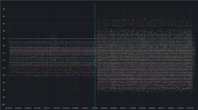
The site on left a big open space with some metal, non heated space (it's cold but above 0°C) with wrought 30 BLE emitters. The one on right is office space with normal temperature with hundreds of BLE advertisers.
Since RSSI uses a noise floor as reference I decided to change it with DTM firmware and emitted a constant carrier on CH 37-39 to see what happens in the office space. And the results looked like in this screenshot.
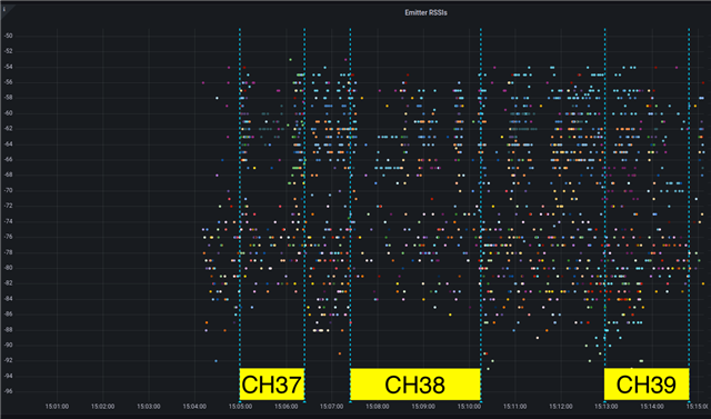
Difference in range is clearly visible, CH37 being the worst offender. Unfortunately I cannot do a similar test on target site.
The reason for writing this message is to maybe understand the RSSI calculation method in more detail than:
RSSI = Prx/PO
where:
• P rx is the received power in watts (W) or decibels (dBm).
• PO is a reference power, often taken to be
And also to see if variables used to calculate the value can be exposed and compensated? For example if BLE channel noise map could be used in side of the application this would make it possible to correct the scanned values, this would be some start. For example can ble_gap_evt_qos_channel_survey_report_t be used for this somehow?
We don't expect RSSI to be ideal or always the same. But same values over >10m distances makes you wonder...

