This post is older than 2 years and might not be relevant anymore
More Info: Consider searching for newer posts

In SPI slave, MISO doesn't work

HW environment :

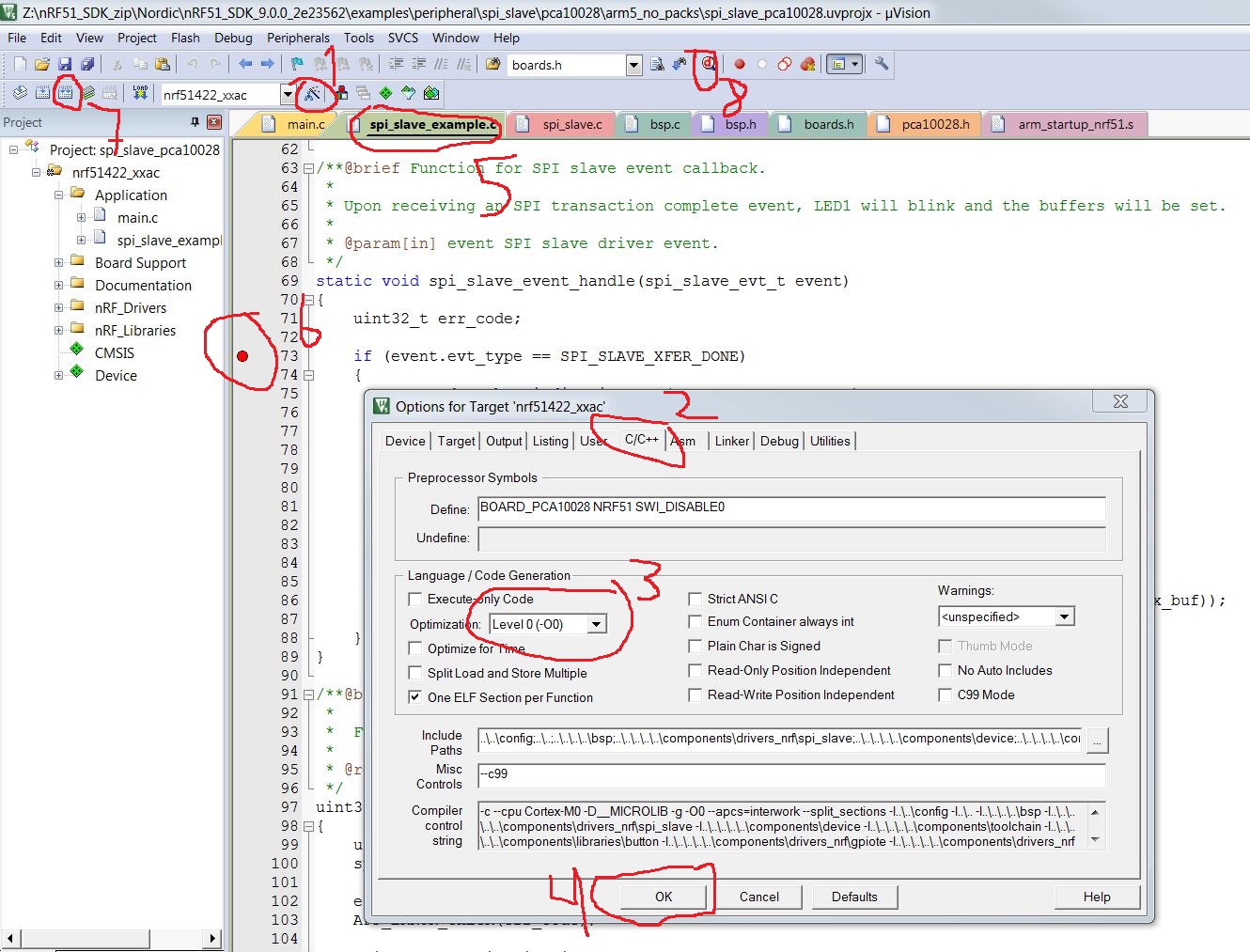
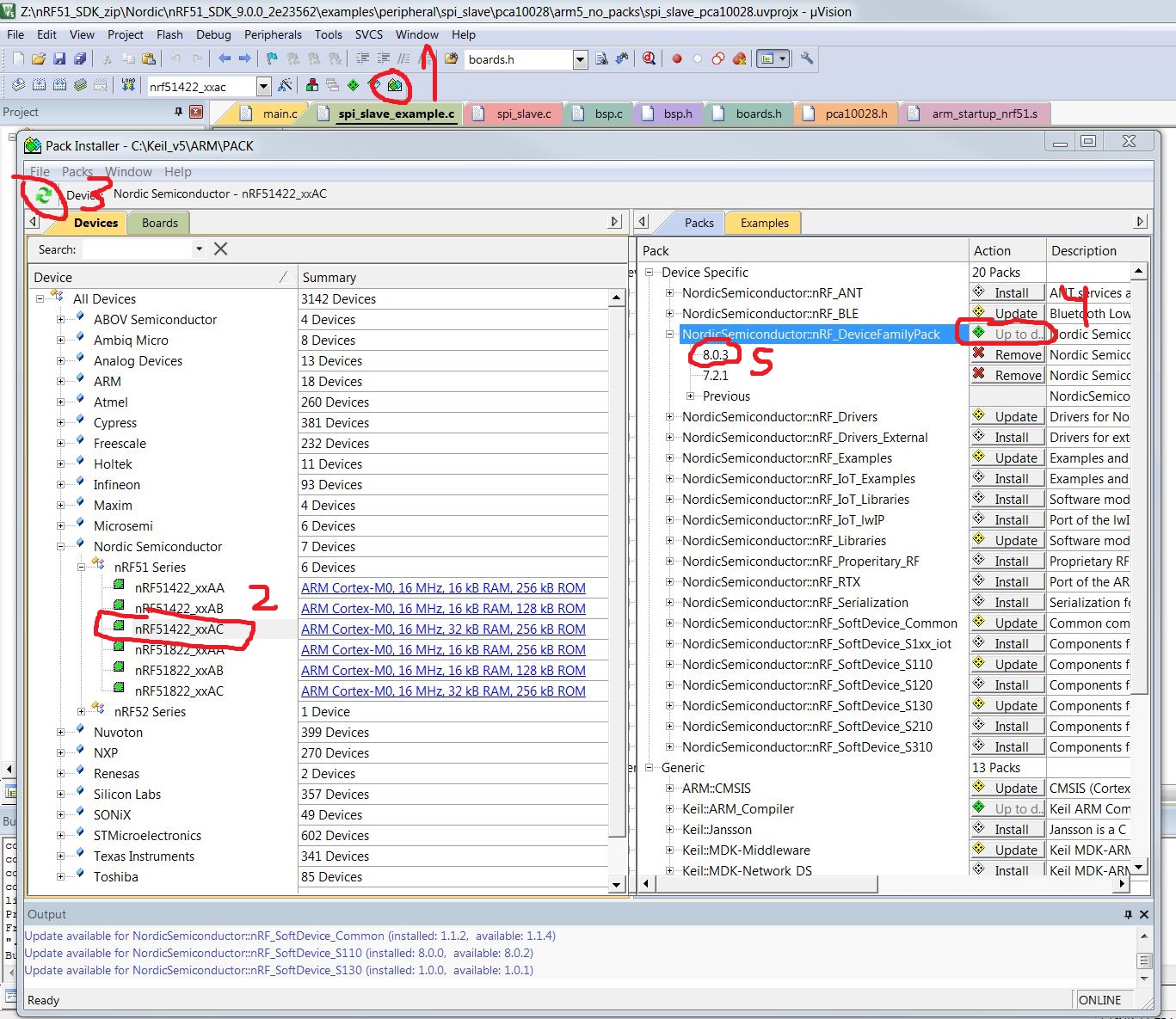
  • SPI Slave : PCA10028 board, and reference source code is 'peripheral/spi_slave' in SDK9.0.0
  • SPI Master : Arduino UNO

Pin setting is below

SPIS_MISO_PIN 28 // SPI MISO signal.

SPIS_CSN_PIN 12 // SPI CSN signal.

SPIS_MOSI_PIN 25 // SPI MOSI signal.

SPIS_SCK_PIN 29 // SPI SCK signal.

I believe there was no pin wiring mistake between two board.

And I could find a code of 'p_tx_buf[i] = (uint8_t)('a' + i);' in the function of 'spi_slave_buffers_init', inside the project 'spi_slave'.

So pca10028 board is believed to send some character pattern like "abcdef...". through MISO line.

But there is no signal from MISO at all.

image description

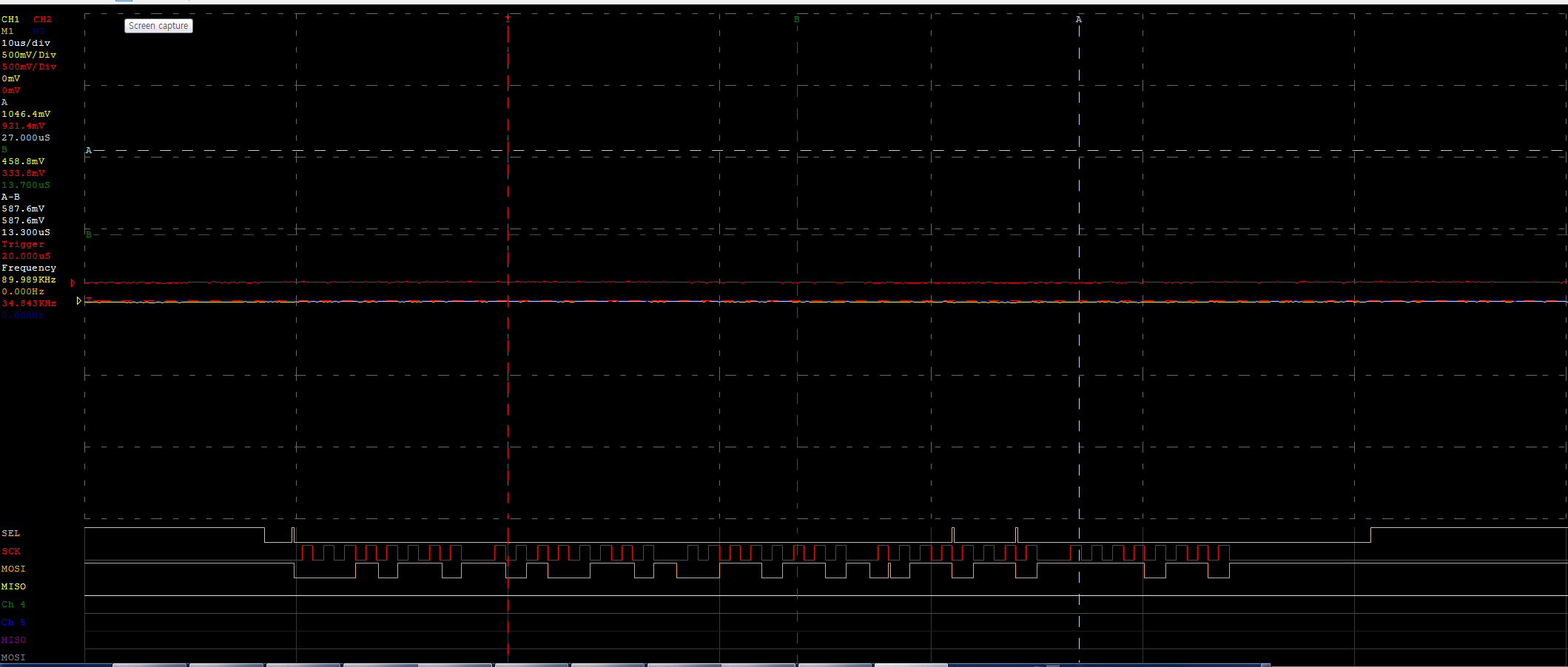
MOSI signal is "hello' with setting of LSB, 1MHz. And it seems no problem. I've tested UNO part source code with another UNO board as a spi slave, and it had no problem.

But now it's not working. I don't understand this situation. Do I have to set the clock of spi slave? if so, how?

  • Hi

    You do not have to set the clock of nRF51's SPI slave. It should output data on MISO when you clock out data on the master, even though you have no data to send on the slave side, it should clock out the ORC character, which is by default in the SDK 9.0.0 example with the value 0x55.

    I assume from your image that SEL line is the chip selects that Arduino sets to start the SPI transaction. What I recognize is that SEL is not constantly low during the transaction. In three places it is toggling to high, like it is floating. the logical analyzer you have can clearly only show high or low and nothing in between. If the actual signal is floating between high and low, the nRF51 might not detect it as low, and in that case, it will not put anything out on MISO. The nRF51 pullup resistor is typically 13kohm. Could there be something creating disturbance on the SEL line, or the Arduino not pulling the SEL line sufficiently?

    Are you receiving any data on the nRF51 side?

    What mode is the SPIS in, i.e. what settings do you have for CPOL adn CPHA? It should match with the SPI configuration on the Arduino.

    Are you using a standard Arduino UNO SPI master example that I could try out? Are you using SPI slave example from SDK 9.0.0 unmodified?

    Update 15.10.2015 To start debugging, you don't have to think about UART. You start with opening the SPIS example in Keil and then you follow the steps as in the following image while having your board connected to your PC via USB

    • Step 1: Remove compiler optimization by choosing Level 0 optimization
    • Step 2: Set the breakpoint where you want the program to halt
    • Step 3: Recompile
    • Step 4: Start debugging, which will automatically flash the code to the board before the actual program execution starts

    image description

    Update 19.10.2015 I suspect you are missing the correct device family pack. you should be using 8.0.3 or later.

    1. Press the pack installer button
    2. Select the nRF51422 QFAC
    3. Download packs updates. Wait for packs to download, progress is shown in the lower right corner.
    4. Press install button for the "NordicSemiConductor:nRF_DeviceFamilyPack"
    5. Verify that DeviceFamilyPack is 8.0.3 or later.

    image description

    Use the nRF51 SDK zip (not packs):

    1. Download SDK 9.0.0 zip (no packs) from developer.nordicsemi.com,
    2. unzip,
    3. browse to the spi_slave example and open the project file,
    4. set up the project for debugging as previously described,
    5. start debugging
  • I reply for the simple question.

    • Polarity and Phase are set to mode 0 at both sides.
    • I'm using the example source of board makers. ==> I used two UNO board to check SPI transaction, of course one is master and the other is slave. It was OK. I replaced UNO slave board with nRF51 board(PCA10028 base). I wired with referring the pinmap of nRF51 board, and also doubled checked the pin map in the header file of the project. So I believe the wiring, example code had no problem.

    It's apparent that SEL signal is not clear. Definitely there is no problem in Arduino source code. I 'll check it later.

    Can't receive data through MISO even though SEL is clear. Please refer to the another capture image.

    https://plus.google.com/photos/116842114539015355819/albums/6205870203837092849/6205870201819796434?pid=6205870201819796434&oid=116842114539015355819

    One more question. Can I check the data nRF51 board received? If it were possible, I could debug more closely.

  • When the CSN (SEL) line goes high the transaction ends you get a callback in the registered SPIS handler, namely the spi_slave_event_handle in spi_slave_example.c. If you start the debugger and set a breakpoint in the handler, you should capture any completed transaction. In the handler you can check if there is any data received by checking the event.rx_amount.

  • You should give the SPI slave at least 7.1 us from setting the SEL line low until starting to clock out data. Looks like from your image that the Arduino is only letting ~2us pass until clocking out data.

  • OK I'll keep SEL low for over 7.1 us later.

    I have a problem. In my KEIL compiler, build/flash download are OK, but debugging is not available. And also I don't know how to receive uart message from the 51422 board.

    This debugging environment is so frustrating. Please help me.

Related