I have made a custom PCB based on nRF52810 SOC. I have started development on Segger Embedded Studio, SDK17.0.1.
I have flashed the GPIO example code to the PCB and it works fine.
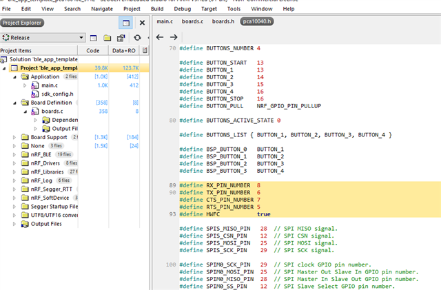
Then I tried the UART example and printf, but in the program. It doesn't show any output to the serial port (used Pin 6 and Pin 8 for UART comm), the same code work perfectly fine for nRF52840DK.
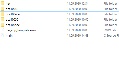
I saw another example project "Template Project", but there is no option for PCA10040e. Doing some testing on which PCA to work with nRF52810 SoC, I found PCA100040e work just fine.
Below code for nRF Logger Configuration.
#include <stdbool.h>
#include <stdint.h>

#include "nrf.h"
#include "nordic_common.h"
#include "boards.h"
#include "nrf_delay.h"

// Must include these headers to work with nrf logger
#include "nrf_log.h"
#include "nrf_log_ctrl.h"
#include "nrf_log_default_backends.h"


/**
 * @brief Function for application main entry.
 */
int main(void)
{

// Initialize the Logger module and check if any error occured during initialization
    APP_ERROR_CHECK(NRF_LOG_INIT(NULL));

	// Initialize the default backends for nrf logger
    NRF_LOG_DEFAULT_BACKENDS_INIT();

	// print the log msg over uart port
    NRF_LOG_INFO("This is log data from nordic device..");

	// a variable to hold counter value
    uint32_t count = 0;


    while (true)
    {	// Dsiplay the logger info with variable
        NRF_LOG_INFO("Counter Value: %d", count);
        nrf_delay_ms(500); // delay for 500 ms
        //count++; // increment the counter by 1
    }
}
/** @} */
Added this part in sdk_config.h
// <e> NRF_LOG_BACKEND_UART_ENABLED - nrf_log_backend_uart - Log UART backend
//==========================================================
#ifndef NRF_LOG_BACKEND_UART_ENABLED
#define NRF_LOG_BACKEND_UART_ENABLED 1
#endif
// <o> NRF_LOG_BACKEND_UART_TX_PIN - UART TX pin
#ifndef NRF_LOG_BACKEND_UART_TX_PIN
#define NRF_LOG_BACKEND_UART_TX_PIN 6
#endif

// <o> NRF_LOG_BACKEND_UART_BAUDRATE  - Default Baudrate

// <323584=> 1200 baud
// <643072=> 2400 baud
// <1290240=> 4800 baud
// <2576384=> 9600 baud
// <3862528=> 14400 baud
// <5152768=> 19200 baud
// <7716864=> 28800 baud
// <10289152=> 38400 baud
// <15400960=> 57600 baud
// <20615168=> 76800 baud
// <30801920=> 115200 baud
// <61865984=> 230400 baud
// <67108864=> 250000 baud
// <121634816=> 460800 baud
// <251658240=> 921600 baud
// <268435456=> 1000000 baud

#ifndef NRF_LOG_BACKEND_UART_BAUDRATE
#define NRF_LOG_BACKEND_UART_BAUDRATE 30801920
#endif

// <o> NRF_LOG_BACKEND_UART_TEMP_BUFFER_SIZE - Size of buffer for partially processed strings.
// <i> Size of the buffer is a trade-off between RAM usage and processing.
// <i> if buffer is smaller then strings will often be fragmented.
// <i> It is recommended to use size which will fit typical log and only the
// <i> longer one will be fragmented.

#ifndef NRF_LOG_BACKEND_UART_TEMP_BUFFER_SIZE
#define NRF_LOG_BACKEND_UART_TEMP_BUFFER_SIZE 64
#endif

// </e>
nRF Logger works fine with nRF52840DK, so is there a way I can use "template_project" example and start development for nRF52810 Soc on my Custom PCB?