SPI-NOR flash devicetree error int_res==16 EBUSY

Dear Nordic Team,

I found a few similar issues in this forum but nothing that then solved my problem which brought me to the conclusion it might be different here.

I try to add an external SPI-NOR flash (MX25R8035F) to nrf52832 project. I started with the example in zephyr/samples/drivers/spi_flash which is for nrf52840 and changed the dts file as follows:


Here I post the "arduino-spi", I also tried with SPI0 and SPI1, same behavior.

nrf52dk_nrf52832.dts:

aliases {
 ...

 ...
spi-flash0 = &mx25r80;
};

arduino_spi: &spi2 {
status = "okay";
cs-gpios = <&gpio0 20 GPIO_ACTIVE_LOW>;
pinctrl-0 = <&spi2_default>;
pinctrl-1 = <&spi2_sleep>;
pinctrl-names = "default", "sleep";

mx25r80: mx25r8035f@0 {
compatible = "jedec,spi-nor";
label="MX25R80";
reg = <0>;
spi-max-frequency = <33000000>;
size = <0x800000>;
jedec-id = [c2 28 14];
};
};

my code:

const struct device *flash_dev = DEVICE_DT_GET(DT_ALIAS(spi_flash0));

void main(void)
{
    if (!device_is_ready(flash_dev)) {
        printk("%s: device not ready.\n", flash_dev->name);
    }
    ...
}


The problem:
The flash device gets partly  initialized since flash_dev.state.initialized == 1 and partly not since flash_dev.state.init_res==16 (should be 0). That is why device_is_ready() return false.
I see this in the debugger as below:
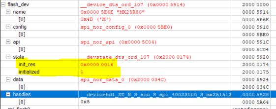


I see on my oszilloscope that SPI itself is working because I get responses from the external flash, so I can't be doing everything wrong. But the write and read process is working incorrectly, meaning that if I write something to a location, I get a wrong response when reading again.

Do you have any ideas what the problem could be? 
I also tried to research what EBUSY in the devicetree means in general and found that it often has to do with wrong pins. However, this can't be the case here, since my SPI is working, do you agree?

Thank you very much in advance,
Joanna

  • Hi Joanna

    Due to the Easter holiday we are rather short on staff, so delayed replies must be expected. I've not been able to review the screenshots as of yet, but I notice you say that you're sending data with a voltage level of 5V when using the Arduino. The MX25R8035F only seem to support operational voltages up to 3.6V, so are you still using this external flash, or are you using some other board with the Arduino?

    I'll investigate if we're able to view the psdata files somehow on our end. I think you should be able to upload them in a .zip folder here on DevZone.

    Best regards,

    Simon

  • Hi Simon,

    yes, I am still using the  MX25R8035F. I supply it with 3.3V, but the signals the Arduino sends are 5V-level and the reply from the flash is level 3.3V. I am aware that this does not comply to the datasheet, but out of desperation I gave it a try and it works...


    Here are the .psdata files as .zip folder. Let me know, if you can't open them.

    psdata-files.zip

    Regards,
    Joanna


  • Hi 

    Sorry about the late update, but we've been delayed by Easter and myself being sick the last days. And now I need to get a green light from our IT department in order to get the program I need to open the psdata files correctly, as we'd like to take a closer look at these plots. 

    Do you know what the 0xFF commando here does? It seems very strange that the same flash chip doesn't respond to the 9F command with dfferent data from the nRF and the Arduino device.

    Thank you for your patience!

    Simon

  • Hi

    Okay, so we found something we should have spotted earlier, and it seems like the two last bits of the JEDEC ID on the nRF side of things are shifted to the left from slave to master. It seems like the 0xC is not shifted though, and that the nRF is just able to sample that pin before it goes low, but it's strange that the slave loses a bit and clocks out the JEDEC code one byte too early.

    Can you send us a picture of how the nRF and flash device are set up and connected? Bit shifts like this are common in bad connections between master and slave or much capacitance on the lines for example, and since the rise time on the nRF52 trace is much slower than on the Arduino setup, one guess is that the wires between them is too long. But then again you shouldn't see the issue when running on lower frequencies if that's the issue.

    Best regards,

    Simon

  • Hi Simon,

    I was also sick for a few days and am only back today...

    1) The 0xFF is not part of any command, I think. It is just what is on the MOSI line while the master is reading the slave answer. For the arduino it is 0x00 and for the nRF 0xFF, I don't think this should matter.

    2) Yes, you're right, the data is shifted. But, it is not always wrong in the same way. The false data is sometimes this and sometimes other things. Nevertheless, of course, it means that data is clocked out incorrectly. Expecially, if the edges are wrong, then it may read sometimes this and sometimes that.

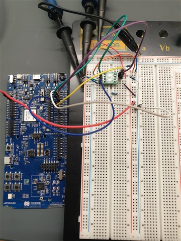
    3) Here is a picture. I attach everything via jumper wires.


    4) I got a hint from one of your FAEs here in Germany and he proposed to add pull-down resistors to MOSI and MISO as well as a pull-up to CS (all 10kOhm). This strangely made it work "for a while", meaning I was able to read the correct data about 20 times. Then I starting "playing around" again with oscilloscope, rearranging some wires and now it stopped working again. There is nothing particular that I have different now. Also I waited 2h for possible capacities to unload, still not working anymore... I wonder what did the trick for that short moment.


    Best regards,
    Joanna 


Related