Unable To Connect To Custom nRF53840 Board

Hi,

We have encountered an issue while trying to flash our custom nRF53840 board using the debug out (P19) on another nRF53840 DK as a programmer. Previously, we were able to flash a nRF52840 custom board using the debug out (P19) on an external nRF52840 DK without any problems. On both programming boards, we have soldered SB47 to provide power to our custom board.

When the custom board is connected we can use jlink viewer to check if there is a valid connection between nRF52840 DK and our nRF52840 custom board. If there isn't a successful connection, we get an error message saying "Could not connect to target. The same thing happens when we try to flash using the nRF52840  DK with SB47 soldered. If our nRF52840 custom board is connected to the debug out, we can flash it successfully. Otherwise, we get an error message saying flashing has failed. This all seems like the correct behaviour as the DK data sheet says the following; "While SB47 is shorted, it is not possible to program the onboard nRF52840 SoC even if the external board is unplugged".

However, the nRF53840 DK behaves differently. With SB47 shorted on the nRF53840 DK, connection through RTT viewer or flashing via vs code (west) is successful even if nothing connected on the debug out (P19). What could the DK be flashing if there is nothing connected on the debug out with SB47 shorted? Could this just be different behaviour between the nRF52840 and nRF53840 DKs?

Despite this difference, we are still able to successfully flash an external nRF53840 DK via the debug in connector from another nRF53840 DK (with SB47 shorted). I have included an image below of this setup.
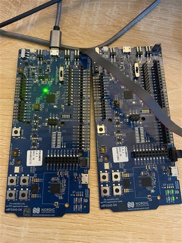
From this image we can see only the external board only has been flashed, as indicated by the firmware switches on LED 1, 2, and 3 on the DK.

However when we try the same setup replacing the external DK with our custom nRF53840 board using a programming jig for SWDIO, SWDCLK, VCC and GND it did not flash our nRF53840 custom board. It did not seem to flash the internal nRF53840 on the DK either, but it gave a flashing successful message. We've also tried reading the INFO.DEVICEID[n]  using nrfjprog, but we only got a unique device ID when a DK was the external board. When the custom board was connected, we got the same value as when no board was connected.

On our custom board we are using a High Voltage DC/DC setup with a supply voltage ranging from 2V to 3.7V (battery powered). We've tried using VDD supplied from the programming DK or by providing power from a constant external source(3.6V) with VDD on the programming pins disconnected, but neither worked. The pins we use for programming are SWDIO, SWDCLK, VDDH and GND.  RESET is not connected, is this needed?

I've attached the schematics for our custom board below .
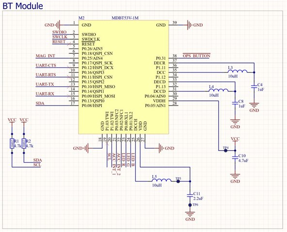
We're using this Raytac module.

Below is Raytac's recommended circuit design for high voltage input.
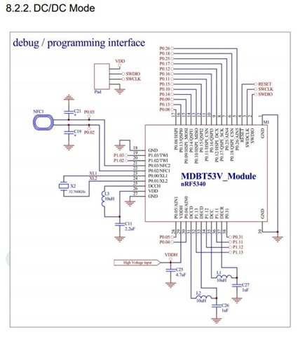
Another important thing to note is our board does not contain an external LFCLK.

Can you see any issues in our HW design?

Thanks in advance for your help.

  • Hi,

    I have started looking into your case. I will get back to you tomorrow.

    Best regards,
    Dejan

  • Hi,

    However when we try the same setup replacing the external DK with our custom nRF53840 board using a programming jig for SWDIO, SWDCLK, VCC and GND it did not flash our nRF53840 custom board. It did not seem to flash the internal nRF53840 on the DK either, but it gave a flashing successful message. We've also tried reading the INFO.DEVICEID[n]  using nrfjprog, but we only got a unique device ID when a DK was the external board. When the custom board was connected, we got the same value as when no board was connected.

    There is a different behavior between nRF52840-DK and nRF5340-DK boards related to debug out and the detection of the external board. Detection method has changed with a change of interface MCU chip.

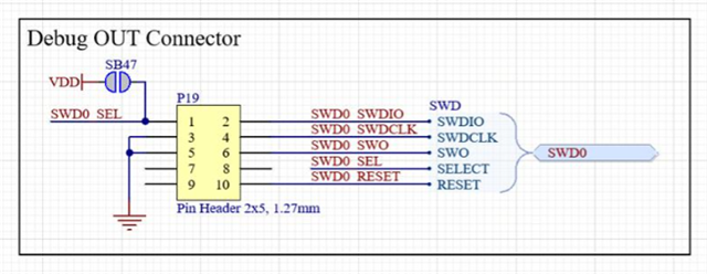
    As you can see from the picture below, in the older version of nRF52840 (and nRF5340), when SB47 is shorted, then SWD0 SEL line is put to VDD which selects an external board. In this case, even if you disconnect external board, selection pin stays high which indicates the existence of the external board.

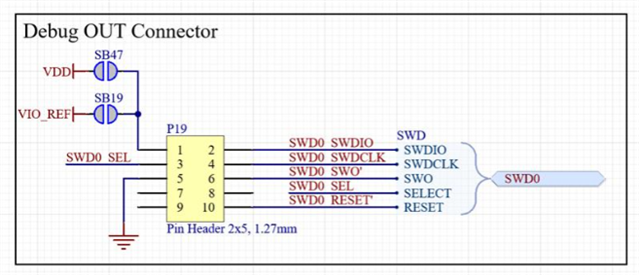
    Situation has changed with newer version of the nRF5340-DK (from v2.0.0) as shown in the picture below. SWD0 SEL is now located at the pin 3 and it is not directly connected to VDD. The selection of external board is done when SWD0 SEL pin is put to the ground. Therefore, if you want to have the same behavior as with older versions of the boards described above, you would need to ground SWD0 SEL pin by changing your custom board, or by modifying the cable by connecting SWD0 SEL to the ground.


    However, if you put pin 3 to the ground and use external power supply of 3.6 V, there would still be a problem because GPIO pins should be supplied with 3 V. GPIO high voltage is tied to VDD. If there is 3.6 V which is supplied to VDDH, this voltage is regulated down to 1.8 V on the VDD pin (as shown for the register VREGHVOUT in the UICR on the application core), but you would need 3 V on VDD to be able to program the device using DK. 

    There are two options. One option would be to supply 3 V directly to VDD (not VDDH) through TP5 when programming, but this would need to be done every time when you program. Second option would be to use external debugger which can program using GPIO voltage of 1.8 V. 

    The pins we use for programming are SWDIO, SWDCLK, VDDH and GND.  RESET is not connected, is this needed?

    It is not needed to have RESET connected. You would need to connect SWDIO, SWDCLK, VDD and GND.

    Can you see any issues in our HW design?

    HW design looks fine.

    Best regards,
    Dejan

  • Hi Dejan,

    Thanks for looking into this.

    I see. So with the nRF53840 DK as a programmer, power will need to be supplied via VDD for connection/flashing our custom board? Then VDDH can be used for normal operation after flashing the firmware.

    Also, when powering our nRF52840 custom board via VDDH is VDD regulated to 1.8V too or is this behaviour only seen on the nRF53840 modules?

  • Hi,

    hugzy123 said:
    I see. So with the nRF53840 DK as a programmer, power will need to be supplied via VDD for connection/flashing our custom board? Then VDDH can be used for normal operation after flashing the firmware.

    Yes, this is correct.

    hugzy123 said:
    Also, when powering our nRF52840 custom board via VDDH is VDD regulated to 1.8V too or is this behaviour only seen on the nRF53840 modules?

    This behavior exists on both nRF5340 and nRF52840. You can read more in registers section of the documentation. Relevant registers are VREGHVOUT for nRF5340 and REGOUT0 for nRF52840.

    Best regards,
    Dejan

Related