Dear Nordic Semiconductors Team,
I am writing to inform you of the changes that have been made to the BLE nRF5280 dongle PCB schematic and layout design that were obtained from Nordic Altium Designer files.
The changes made to the schematic diagram involved adding a battery holder component and removing USB components and other non-used components such as push buttons. were also adjusted to suit the new design. These changes were necessary to meet the specific requirements of our project.
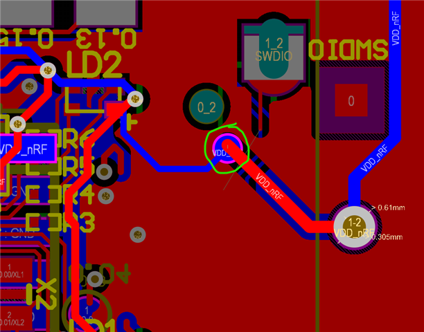
Furthermore, we have also made changes to the PCB layout to fit the battery holder in the designated location. The dimensions of the PCB were adjusted, and the component placement and routing of the traces were modified to accommodate the changes made to the schematic diagram. Lastly, the BOM was updated accordingly to reflect the changes made to the PCB layout.
NOTE, The coin battery to be used supplies a 3.3V as I am aware that the USB previously supplied 5V to power the ble device therefore I have modified resistor R7 value to be 0 ohms. please verify
We kindly request your assistance in verifying the changes we have made to the device PCB. Please review the modifications we have made to the schematic diagram, PCB layout, and BOM to ensure that they meet the required standards and specifications.
Thank you for your cooperation, and we look forward to hearing from you soon.
kindly find the attached modified Altium designer zipped files
Best regards, [Ahmed Salah ]
nRF52840 USB Dongle - Hardware files (modified).zip


