Schematic review

Good morning, 
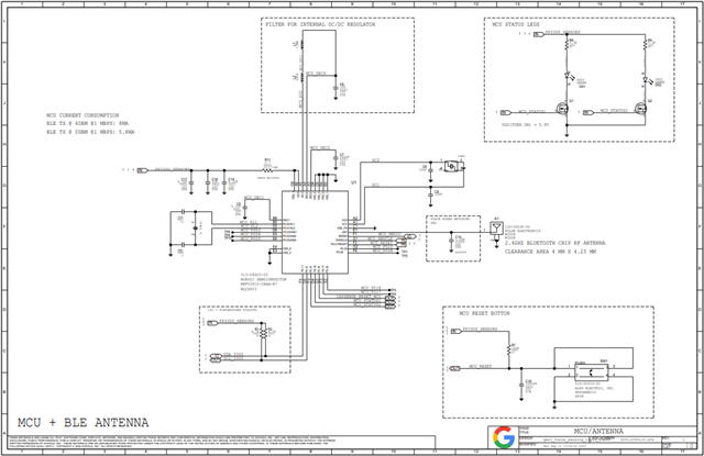
I ended up changing the design to use the nRF52810 chipset and I wanted to find out if Nordic would be able to provide some schematic feedback for my design. Below is the schematic: 
I have a couple of questions I wanted clarified: 
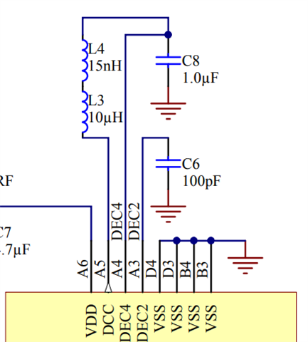
1. On the reference design you have a 10uH and a 15nH inductor in series for the DC/DC regulator filter. Is the 15nH inductor necessary? 
2. I have used the following xtal crystals for the 32.768Hz and the 32MHz frequencies respectively: 9H03280012, and 8Q32070006. Will these work well for your chipset? Also recommended known ones you have used in the past if these don't work. 
3. I am using this chip antenna on the board, let me know if you foresee any issues with this: w3008
Looking forward to hearing from you. 
Many thanks 
Tinashe
Google
Parents
  • Hello,

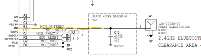
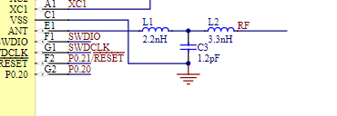
    I have checked the schematic. There is not matching network for radio. You can look at our reference design to see the matching components for Radio. 

    The VSS pin is also not grounded through the capacitor C3 as like as reference design.


    Here are the answers of your questions:

    1.  On the reference design you have a 10uH and a 15nH inductor in series for the DC/DC regulator filter. Is the 15nH inductor necessary? 

    The high frequency 15 nH inductor is used to filter high frequency noise from the DCDC converter that can affect the receiver. This is important to achieve the specified RX sensitivity. 

    2. I have used the following xtal crystals for the 32.768Hz and the 32MHz frequencies respectively: 9H03280012, and 8Q32070006. Will these work well for your chipset? Also recommended known ones you have used in the past if these don't work. 

    I am not able to find any datasheet that matches the two crystals that you have shared. Can you share the data sheet with me so that I can be sure that I am not reading the wrong documentation found? We have our crystal specifications here (https://infocenter.nordicsemi.com/topic/ps_nrf52810/clock.html?cp=4_5_0_4_3_3_1#unique_1332589092) and (https://infocenter.nordicsemi.com/topic/ps_nrf52810/clock.html?cp=4_5_0_4_3_3_3#unique_915206003) which you also can see to match your crystal specification. 

    3. I am using this chip antenna on the board, let me know if you foresee any issues with this: w3008

    Yes, You can use chip antenna mounted on the board. Currently you have one shunt capacitor which is ok. It might be nice to add a full pi or T network for matching. 

    Thnaks.

    Best Regards,

    Kazi Afroza Sultana

Reply
  • Hello,

    I have checked the schematic. There is not matching network for radio. You can look at our reference design to see the matching components for Radio. 

    The VSS pin is also not grounded through the capacitor C3 as like as reference design.


    Here are the answers of your questions:

    1.  On the reference design you have a 10uH and a 15nH inductor in series for the DC/DC regulator filter. Is the 15nH inductor necessary? 

    The high frequency 15 nH inductor is used to filter high frequency noise from the DCDC converter that can affect the receiver. This is important to achieve the specified RX sensitivity. 

    2. I have used the following xtal crystals for the 32.768Hz and the 32MHz frequencies respectively: 9H03280012, and 8Q32070006. Will these work well for your chipset? Also recommended known ones you have used in the past if these don't work. 

    I am not able to find any datasheet that matches the two crystals that you have shared. Can you share the data sheet with me so that I can be sure that I am not reading the wrong documentation found? We have our crystal specifications here (https://infocenter.nordicsemi.com/topic/ps_nrf52810/clock.html?cp=4_5_0_4_3_3_1#unique_1332589092) and (https://infocenter.nordicsemi.com/topic/ps_nrf52810/clock.html?cp=4_5_0_4_3_3_3#unique_915206003) which you also can see to match your crystal specification. 

    3. I am using this chip antenna on the board, let me know if you foresee any issues with this: w3008

    Yes, You can use chip antenna mounted on the board. Currently you have one shunt capacitor which is ok. It might be nice to add a full pi or T network for matching. 

    Thnaks.

    Best Regards,

    Kazi Afroza Sultana

Children
No Data
Related