Understanding DTS and configuration

I am working my way through the nRF Connect SDK Fundamentals usin NRF52840DK (PCA10040) board.

The led blinky works OK, but looking at the DTS file, I can see that LED0 is defined as gpio0 13:

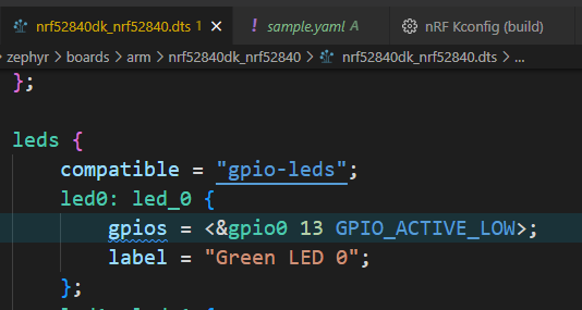
which is incorrect as LED0 is gpio0 pin 17.

However in the main.c it gets the correct value of pin 17, and it works.

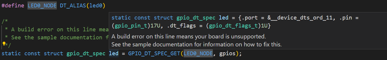
How is that? what am I missing?

Thanks

Johanan

Parents
  • If you have PCA10040, then that is not an nrf52840. PCA10040 is an NRF52 dev kit that supports the nrf52832.

    LED0 on the nrf52840 is pin 13 like the DTS says, and if you compile it for an nrf52840 board then it does not change to pin 17 and it works. If you compile for an nrf52832, then main.c says pin 17 and so does the .dts file for an nrf52832. My guess is you are compiling for the nrf52832 but are looking at the nrf52840 .dts file.

Reply
  • If you have PCA10040, then that is not an nrf52840. PCA10040 is an NRF52 dev kit that supports the nrf52832.

    LED0 on the nrf52840 is pin 13 like the DTS says, and if you compile it for an nrf52840 board then it does not change to pin 17 and it works. If you compile for an nrf52832, then main.c says pin 17 and so does the .dts file for an nrf52832. My guess is you are compiling for the nrf52832 but are looking at the nrf52840 .dts file.

Children
Related