Enabling GPS external antenna on thingy91

Hi,

I am using Thingy91 v1.6.0.

SDK : v2.2.0

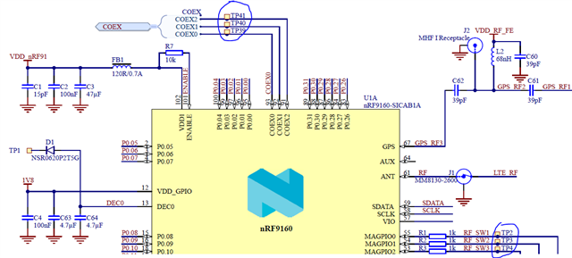
I want to use an external antenna for GPS. The antenna I am using is: robu.in/.../

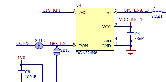
I connected the external antenna to the UFL connector labelled GPS on thingy91 board.

In the sample gnss, I modified below configuration:

"CONFIG_MODEM_ANTENNA=y

CONFIG_MODEM_ANTENNA_GNSS_ONBOARD=n

CONFIG_MODEM_ANTENNA_GNSS_EXTERNAL=y

CONFIG_MODEM_ANTENNA_AT_COEX0="AT%XCOEX0"
"

Now, when I build the code and flash to thingy91, I am not able to see any improvement in GPS receiving.

So, are above configurations correct or am I missing something?

How should I confirm if the antenna was switched to external sucessfully ?

Regards,

engineerN

Parents Reply Children
  • Hi Nikhil,

    Simon is out-of-office till next week.

    Nonetheless, I have few comments about your conversations.

    The antenna you are using is Active antenna, while you have mentioned it is passive antenna.

    There are two (general) types:
    Active antenna: those which have LNA part built-in
    Passive antenna: those which do not have an LNA

    Therefore, to use an active antenna, you need to turn off the LNA on the thingy91.
    However, LNA on your antenna would also require power.

    Therefore, there are following considerations:
    1) COEX0 need to be disabled (to turn off the LNA of thingy91)
    2) COEX2 will be pulled high (to turn on the DC current to power LNA of your external antenna)

    The board files (nrf/boards/arm/thingy91...) changes are not required as those changes are to be done using the config options.

    Please use following configurations:

    CONFIG_NRF_MODEM_LIB=y #to use Nordic modem library
    CONFIG_MODEM_ANTENNA=y #to use modem antenna library/functionality
    CONFIG_MODEM_ANTENNA_GNSS_ONBOARD=n #to disable onboard antenna
    CONFIG_MODEM_ANTENNA_GNSS_EXTERNAL=y #to enable external antenna
    CONFIG_MODEM_ANTENNA_AT_COEX0="AT%XCOEX0" #to disable onboard LNA

    The AT command %XCOEX0 writes the COEX0 pin configuration to device's RAM.
    The COEX0 pin can be configured to switch its state based on the modem's RF frequency, for example,
    to enable external Low-Noise Amplifier (LNA) in GNSS mode.


    The basic configuration (AT%XCOEX0) will delete previous values stored in RAM.
    The following command example sets COEX0 to 1 when GNSS is enabled (and 0 when GNSS is off):

    AT%XCOEX0=1,1,1570,1580

    where the first '1' means one-range of frequency, and the second '1' means active state of COEX0 for this range, and last two parameters are the low and high frequency ranges.

    You can try reading the state of COEX0 using read-command. However, you will see it will produce error if it is not already set. Moreover, it must be set at the start (when modem is turned on) before any other modem activity. (So the modem must be active and set it before any other modem activity).

    You may also read (and try) %XMAGPIO command which configures/controls multiple pins.

    AT Commands

    From 9160 SoC documentation (nrf9160_COEX) we see that:

    The COEX interface consists of pins 91–93. It is dedicated for RF interference avoidance towards a companion radio device, such as an external positioning device or BLE. To control the COEX interface, the LTE modem must be active. When the LTE modem is not active, the COEX interface floats.

    The COEX pins have the following functionalities:

    COEX0 (pin 93) Can be configured for external Global Positioning System (GPS) Low-Noise Amplifier (LNA) control (high state) during GPS receive.
    COEX2 (pin 91) Can be used as an indicator of LTE or GPS RF activity from the modem to an external device.
    When COEX2 is high, the LTE or GPS RF is active, and when it is low, the LTE or GPS RF is inactive.

    AT commands like %XRFTEST and %XMAGPIO may also be useful. 

    Regards,
    Naeem

  • Hi Naeem,

    I created a thingy91_nrf9160_ns.conf file in boards directory.

    In that I added the above mentioned configs. The configs are reflecting as I can see the respective values changed in .config file under build directory after build.

    In the .config file I saw one config:

    CONFIG_MODEM_ANTENNA_AT_MAGPIO="AT%XMAGPIO=1,1,1,7,1,746,803,2,698,748,2,1710,2200,3,824,894,4,880,960,5,791,849,7,1565,1586"
    Is there any need to make any change above config?


    I tested the AT commands and below are their response:

    AT%XRFTEST


    ERROR


    AT%XMAGPIO


    OK

    What does this means?

    How should I confirm if the antenna switching is taking place?

    Performance wise I am not seeing any change.

    Regards,

    engineerN

  • Hi

    engineerN said:
    The configs are reflecting as I can see the respective values changed in .config file

    Yes, thats one way to check what settings/configuration are going to take place.

    As said previously, COEX0 need to be disabled to turn-off internal LNA

    (U4 is onboard LNA and disabling COEX0 will disable it)

    Next, to improve antenna efficiency, Nordic Thingy:91 has dynamic antenna tuning. Different tuning components are used for different frequencies. This is achieved by using tuning components between two switches (U2 and U3 on thingy91).

    The switches are automatically controlled by the nRF9160 LTE modem and set to the correct state based on the frequency of operation. Six paths are used for LTE frequency, and one path is used for GPS frequency.

    So for GPS, we would need all three switches (RF_SW1, 2 and 3) to be enabled / 1.

    This is done through the %MAGPIO AT command.

    engineerN said:
    AT%XMAGPIO=1,1,1,7,1,746,803,2,698,748,2,1710,2200,3,824,894,4,880,960,5,791,849,7,1565,1586

    So this command is configuring MAGPIO pins (0,1,2), and setting 7 frequency bands.

    The MAGPIO are used, for example, to control an external antenna tuner, or any other device, whose state depends on modem's RF frequency. The %XMAGPIO command needs to be sent before any modem activity occurs. Based on the given configuration, the modem applies the MAGPIO state corresponding to the RF frequency range automatically during runtime.

    You can issue AT commands through LTE link monitor. You are missing a "?" at the end of AT command to read the state; otherwise, the command you have issued will delete all previous configuration.

    So to read the configuration:

    Moreover, you can test the state of these pins by checking test points on thingy91.

    TP39, TP40, TP41 for COEX0, COEX1, COEX2

    TP2, TP3, TP4 for MAGPIO0, MAGPIO1, MAGPIO2

    Regarding XRFTEST, you are not using it correctly. Also, this AT command cannot be used if the modem has already been activated with the %CFUN command.

    I recommend you to look at AT commands and then use them.

    Please take care of notes mentioned before usage of AT commands.

    Regards,

    Naeem

Related