This post is older than 2 years and might not be relevant anymore
More Info: Consider searching for newer posts

Problems with SPI on NRF52, no signal

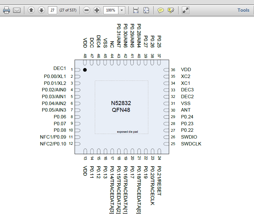
We are running tests using the spi_master_with_spi_slave example and using an oscilloscope to see if we are getting any signal from the clock or the MOSI but we have not received any signal, we also tried the spi_master example and got nothing. No waveform just flat line. We are following an image of the board and its pins, compared with the code we noticed that SCK is set to pin 29 which corresponds to the pin assignment of P0.24 on the nRF52832 OPS sheet.

Here is an image: image description

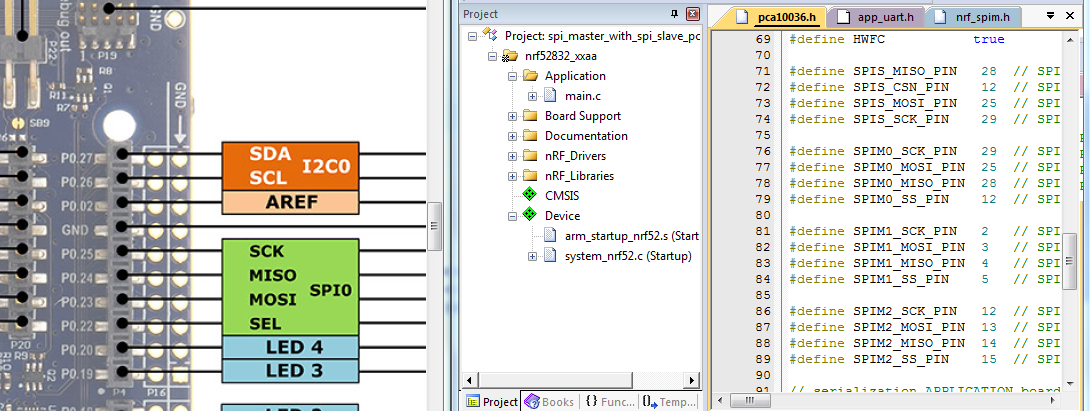
The pin assignment we are following is: image description

We were hoping someone here could help us figure out what the issue is or what we are doing wrong. There have been no changes made to the code.

Thank you in advance

Parents
  • I think you have misunderstood the pin numbering convention. The pin number defines in the pca10028.h file are referring to the GPIO pin numbers, not the sequential numbering of the physical pins around the chip. I.e. with the connections shown in your image use these pin defines:

    #define SPIM0_SCK_PIN       25     /**< SPI clock GPIO pin number. */
    #define SPIM0_MOSI_PIN      23     /**< SPI Master Out Slave In GPIO pin number. */
    #define SPIM0_MISO_PIN      24     /**< SPI Master In Slave Out GPIO pin number. */
    #define SPIM0_SS_PIN        22     /**< SPI Slave Select GPIO pin number. */
    

    given that you are using SPIM0 as your image suggest.

    This numbering convention is used to make it easier to manipulate multiple GPIO pins at the same time without having to worry about where the VDD pins, VSS pins, etc are.

Reply Children
No Data
Related