nrf21540 working confirmation

Hi All!

I am using nrf21540DK, NCS version 2.3.0, Radio Test example, RSSI Viewer as a Scanner, and VSCODE studio as an IDE. 

I am getting -23dbm when set to nrf52840 at -4 to 4dbm and -46dbm when setting nrf52840 at -20dbm. The distance between Scanner (nrf52833 connected to RSSI Viewer) and nrf21540 is 1 Meter almost.

I want to confirm that nrf21540 is working properly and reading out the internal registers like CONFREG0-3. Can you please help me with that 

1)how to read them via SPI any code example?

2)As we are configuring the nrf21540 in Radio test example via UART commands (like output_power pos8dBm,start_channel 20 , and start_tx_sweep, etc) .So we are basically configuring these registers . Can you help me to find out where we can read those registers (CONFREG0-3) in the Radio test example?

3)I am also testing the custom board (nrf21540 + nrf52833).I configured pins according to our design but got -67dbm. This means nrf21540 is not working properly So to ensure that nrf21540 registers are properly configured, I need the above-mentioned point # 1-2 suggestions/solutions if possible. 

Thanks & Regards,

Muhammad Usman

Parents
  • Hi 

    The radio_test sample doesn't officially support the nRF21540DK, and I think it will require some modifications in order to work properly with this board. I will do some checking internally to see if someone else has made this work and get back to you.  

    In the mean time, would you be able to test the Direct Test Mode sample instead?

    This sample properly supports the nRF21540DK, and you can use the Direct Test Mode app in nRF Connect for Desktop to control the board over USB. 

    Best regards
    Torbjørn

  • Hi 

    Thank you for the response! Sure I will try to test with it 

    I have some confusion. Can you please guide me,

    1)I tried my custom board (nrf52833+nrf21540) with the following example to add the FEM 

    https://developer.nordicsemi.com/nRF_Connect_SDK/doc/latest/nrf/samples/bluetooth/peripheral_uart/README.html

    But faced the same issue as mentioned above. 

    2)Some people are testing it, nrf21540DK with a radio test example in the following link 

     nrf21540 gain always 20dB 

    3)My requirement is to Increase the signal strength will "Direct test mode Sample" help me with that? Eventually, I have to run it to my custom board(nrf52833+nrf21540) with my main BLE project. Will you guide me that how to integrate that sample into my project(For example in peripheral uart) ?

    Thanks & regards,

    Muhammad Usman

  • Hi Muhammad

    I have to rectify my previous response a bit. 

    While the nRF21540DK is not listed as one of the supported boards for the radio_test sample it does actually work, you just need to enable the FEM device yourself by adding CONFIG_FEM=y to your prj.conf file. 

    Once this is done you can then run some additional commands which will allow you to set the gain of the nRF21540. 

    If you press tab after flashing the board with CONFIG_FEM set you will notice that there are some more commands available, such as the total_output_power setting. This setting allows you to set the output power on the antenna, which will be the sum of the output power set in the nRF52 and the nRF21540 (the libraries will decide which values to set in each device to reach the target output power). 

    If you set the total_output_power to 20 you should see a stronger signal. 

    Finally, I don't think you can trust the RSSI viewer too much when the incoming signal is very strong (> -20dBm). This is based on the RSSI feature in the nRF radio, which is not super accurate and will not be able to accurately detect very strong signals. If you want to ensure that you see the difference between enabling the FEM or not I would try to add some attenuation between the DUT and the RSSI receiver in order to keep the incoming signal at a lower level. 

    Muhammad Usman said:
    I have to run it to my custom board(nrf52833+nrf21540) with my main BLE project. Will you guide me that how to integrate that sample into my project(For example in peripheral uart) ?

    Are you planning to make your own custom board files? 

    If you build a Bluetooth sample for the nRF21540DK board then the FEM should automatically be enabled, and no additional step is needed (CONFIG_FEM is only needed in the radio_test sample). 

    If you are making your own custom board you need to ensure that the board files configure the nRF21540 device correctly. 

    Best regards
    Torbjørn

Reply
  • Hi Muhammad

    I have to rectify my previous response a bit. 

    While the nRF21540DK is not listed as one of the supported boards for the radio_test sample it does actually work, you just need to enable the FEM device yourself by adding CONFIG_FEM=y to your prj.conf file. 

    Once this is done you can then run some additional commands which will allow you to set the gain of the nRF21540. 

    If you press tab after flashing the board with CONFIG_FEM set you will notice that there are some more commands available, such as the total_output_power setting. This setting allows you to set the output power on the antenna, which will be the sum of the output power set in the nRF52 and the nRF21540 (the libraries will decide which values to set in each device to reach the target output power). 

    If you set the total_output_power to 20 you should see a stronger signal. 

    Finally, I don't think you can trust the RSSI viewer too much when the incoming signal is very strong (> -20dBm). This is based on the RSSI feature in the nRF radio, which is not super accurate and will not be able to accurately detect very strong signals. If you want to ensure that you see the difference between enabling the FEM or not I would try to add some attenuation between the DUT and the RSSI receiver in order to keep the incoming signal at a lower level. 

    Muhammad Usman said:
    I have to run it to my custom board(nrf52833+nrf21540) with my main BLE project. Will you guide me that how to integrate that sample into my project(For example in peripheral uart) ?

    Are you planning to make your own custom board files? 

    If you build a Bluetooth sample for the nRF21540DK board then the FEM should automatically be enabled, and no additional step is needed (CONFIG_FEM is only needed in the radio_test sample). 

    If you are making your own custom board you need to ensure that the board files configure the nRF21540 device correctly. 

    Best regards
    Torbjørn

Children
  • Hi  

    Thank you so much for the detailed answer.

    Are you planning to make your own custom board files? 

     I configured the project in a .verlay file according to my custom board pin configuration. 

    As you said, RSSI values are not accurate but just for reference whether FEM is working or not I used it. 

    1) nrf21540DK radio test sample gave me a -23dbm. when I disable the FEM it gave me -67dbm almost

    2)But the custom board gave me -66dbm almost. This Means nrf21540 SOC is not working.

    All the above tests were performed at a distance of 1 meter. And nrf52833 output was 0dbm.

    Now question is that, can we make sure that nrf21540 SOC is working by reading 

    1)Its internal registers ? if yes then any direction/ help?

    2)Can I access these values from the radio test sample and print them on UART? As we are configuring the nrf21540 SOC via commands to set the output power and channel selection etc. I tried to find out but fail to find them.

    3)Can u please help me that how to fully enable the radio test example for the nrf21540 Dk / nrf52833+nrf21540 custom board? Yesterday, I monitored (radio test sample) the SPI signals but no signals on the SPI pins. But when I loaded the direct test mode as per your instructions able to see the sck , MISO and MOSI signals.

    Thanks & Regards,

    Muhammad Usman

  • Hi Muhammad

    Are you able to probe the SPI pins with a scope to see if there is any communication happening over the interface?

    How does your overlay look?
    You can use the nrf21540_ek.overlay as reference. 

    I just tried modifying a standard Bluetooth sample to use the nRF21540EK on the nRF52833DK, and all I had to do to make it work was to include that overlay (by setting the SHIELD to nrf21540_ek) and set CONFIG_BT_CTLR_TX_PWR_ANTENNA=20 in my prj.conf file. 

    Best regards
    Torbjørn

  • Hi Torbjørn

    Thank you for the response, yes I tried but there are no signals present on SPI pins (SCK, MISO, MOSI) with the "Radio test sample"

    But when I loaded the "Direct Test Mode" I am able to read the pulses at sck , MOSI, and MOSI as well.

    My .overlay file looks like 

    /*
     * Copyright (c) 2022 Nordic Semiconductor ASA
     *
     * SPDX-License-Identifier: LicenseRef-Nordic-5-Clause
     */
    
    / {
    	chosen {
    		nordic,nus-uart = &uart0;
    	};
    };


    &nrf_radio_fem{
        compatible = "nordic,nrf21540-fem";
        tx-en-gpios = <&gpio0 30 GPIO_ACTIVE_HIGH>;
        rx-en-gpios = <&gpio0 5 GPIO_ACTIVE_HIGH>;
        pdn-gpios = <&gpio0 9 GPIO_ACTIVE_HIGH>;  
    //	ant-sel-gpios = <&gpio0 21 GPIO_ACTIVE_HIGH>; IN HW ant_sel pin is GND
    //    mode-gpios = <&gpio0 19 GPIO_ACTIVE_HIGH>;  IN HW Mode pin is GND
        spi-if = <&nrf_radio_fem_spi>;
        supply-voltage-mv = <3000>;
    };
    
    &fem_spi{
    	status = "okay";
    	cs-gpios = <&gpio0 11 GPIO_ACTIVE_LOW>;  
    
    	pinctrl-0 = <&spi3_default_alt>;
    	pinctrl-1 = <&spi3_sleep_alt>;
    	pinctrl-names = "default", "sleep";
    	nrf_radio_fem_spi: nrf21540_fem_spi@0 {
    		compatible = "nordic,nrf21540-fem-spi";
    		status = "okay";
    		reg = <0>;
    		spi-max-frequency = <8000000>;
    	};
    };
    

    pin_cntrl.dtsi

    // added 
    
    spi3_default_alt: spi3_default_alt {
    		group1 {
    			psels = <NRF_PSEL(SPIM_SCK, 0, 15)>,
    				<NRF_PSEL(SPIM_MISO, 0, 17)>,
    				<NRF_PSEL(SPIM_MOSI, 0, 20)>;
    		};
    	};
    
    	spi3_sleep_alt: spi3_sleep_alt {
    		group1 {
    			psels = <NRF_PSEL(SPIM_SCK, 0, 15)>,
    				<NRF_PSEL(SPIM_MISO, 0, 17)>,
    				<NRF_PSEL(SPIM_MOSI, 0, 20)>;
    			low-power-enable;
    		};
    	};

    .proj_conf 

    CONFIG_MPSL=y
    CONFIG_MPSL_FEM=y
    CONFIG_MPSL_FEM_NRF21540_GPIO_SPI=y
    CONFIG_BT_CTLR_TX_PWR_DYNAMIC_CONTROL=y
    CONFIG_MPSL_FEM_NRF21540_RX_GAIN_DB=0
    CONFIG_MPSL_FEM_NRF21540_TX_GAIN_DB=20
    CONFIG_BT_CTLR_TX_PWR_ANTENNA=20

    Thanks & Regards,

    Muhammad Usman

  • Hi Muhammad

    I can't see that you have set CONFIG_FEM=y in your configuration? 

    As mentioned earlier the radio_test sample will work with the nRF21540, but you need to set this config parameter for the FEM functionality to be enabled. 

    Regular Bluetooth samples does not need this config to be set. 

    Best regards
    Torbjørn

  • Thank you so much for your help! 

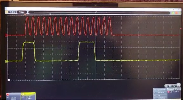
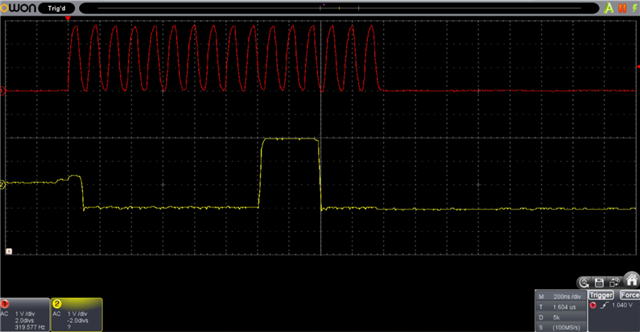
    I tried it just after your response, It's working fine. I am getting the SPI response on MISO and MOSI .

    Clk and MOSI

    Clk and MISO 

    this was the response with nrf2150DK, now need to correlate the results with the custom board.

    Thanks & Regards,

    Muhammad Usman

Related