Hi,
I'm trying to drive an RGB LED on a custom board with NRF 52832. The code is base on the PWM example demo3 from SDK 17.1.0
int main(void)
{

	TestCode();

  /* main loop */
  while (1)
  {

  }
}
void TestCode(void)
 {
				/*
			 * This demo uses only one channel, which is reflected on LED 1.
			 * The LED blinks three times (200 ms on, 200 ms off), then it stays off
			 * for one second.
			 * This scheme is performed three times before the peripheral is stopped.
			 */

			nrf_drv_pwm_config_t const config0 =
			{
					.output_pins =
					{
							23/*|NRF_DRV_PWM_PIN_INVERTED*/, // channel 0
							NRF_DRV_PWM_PIN_NOT_USED,             // channel 1
							NRF_DRV_PWM_PIN_NOT_USED,             // channel 2
							NRF_DRV_PWM_PIN_NOT_USED,             // channel 3
					},
					.irq_priority = APP_IRQ_PRIORITY_LOWEST,
					.base_clock   = NRF_PWM_CLK_8MHz,
					.count_mode   = NRF_PWM_MODE_UP,
					.top_value    = 10,
					.load_mode    = NRF_PWM_LOAD_COMMON,
					.step_mode    = NRF_PWM_STEP_AUTO
			};

			nrf_drv_pwm_init(&m_pwm0, &config0, NULL);


			// This array cannot be allocated on stack (hence "static") and it must
			// be in RAM (hence no "const", though its content is not changed).
			static uint16_t /*const*/ seq_values[] = {0x0004,0x0004,0x0004,0x0004,0x0004,0x0004,0x0004,0x0004,0x0008,
			0x0008,0x0008,0x0008,0x0008,0x0008,0x0008,0x0008,0x0008,0x0008,0x0008,0x0008,0x0008,0x0008,0x0008,0x0008};

			nrf_pwm_sequence_t const seq =
			{
					.values.p_common = seq_values,
					.length          = NRF_PWM_VALUES_LENGTH(seq_values),
					.repeats         = 0,
					.end_delay       = 0
			};

			(void)nrf_drv_pwm_simple_playback(&m_pwm0, &seq, 1, NRF_DRV_PWM_FLAG_STOP);
 }
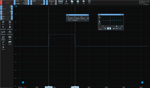
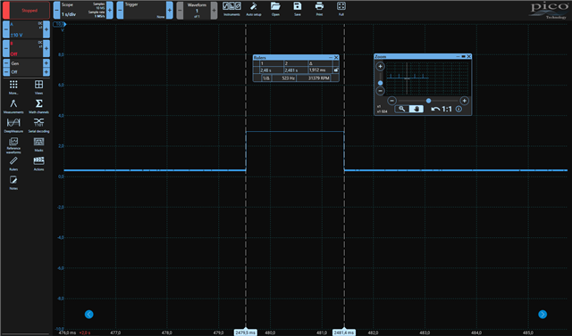
Until now I haven't managed to observe the PWM signal on the scope. I am only getting a single pulse and the LED stays off.
From my understanding:
The PWM frequency is set by the TOP value. At TOP = 10, with 8 Mhz clk (125 ns), this gives a PWM period of 10*125ns = 1.25 us
For each PWM period, a value is retrieved in the sequence list. Starting with 0x0004:
For this value, the MSB is "0" which means the first PWM period start from "0". The duty cycle value is 4,
which means the counter COMPARE register is loaded with this value. When the counter reach the COMPARE value, we get the 1st rising edge of the PWM signal.
The signal stays high until the counter reach TOP = 10 and the high state duration = (TOP-COMP)*Tclk = 6*125ns = 750 ns. Then the counter reset and we get
the 1st falling edge of the PWM signal.
The next value in the list is 0x0004 so the signal stay low until counter = compare once again. This end the 1st PWM period and start the 2nd one...
For the 0x0008 values, the high state duration will last (TOP-COMP)*Tclk = (10-8)*125ns = 250 ns.
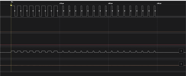
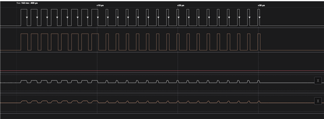
So I am expecting to get a PWM signal with 24 periods. With the 1st 8 periods having a high state duration of 750 ns, and the last 16 periods a high state duration of 250 ns
Any idea on what's going on ?
I've tried testing with the following simplified sequence: "0x0004,0x0008,0x0008" or even "0x8004,0x8008,0x8008" and set seq.repeats = 7 to apply every value 8 times, without results.
But if I add two more values in this simplified sequence: 0x0,0x0004,0x0008,0x0008,0x0 or 0x0,0x0004,0x0000,0x0000,0x0 the LED turns green. But still having a single pulse on the scope
I can't explain why these two extra value are needed.
So, to summup two problems:
- I can't get the full PWM waveform on the scope, I'm only getting a single pulse -> I've tried configuring the pin as output in the begining of main() without results.
- My original sequence is not working as expected.