HI DEVZONE
In this project, RTC1 triggers every 500us, while SPIM3 continuously sends the following data set: command 0x2b, data 0xfA, 0xfC, 0xfD, 0xfE, 0xf8.
During testing, we observed that when the data ends with 0xf8 or 0xf9 (although it is uncertain if only these two values are affected, but 0xf8 and 0xf9 have a high probability), the data sent by SPIM seems to be easily interrupted by RTC interrupts, despite there being no apparent relationship between them. When capturing the data with a logic analyzer, we always found the sending data is incorrect.
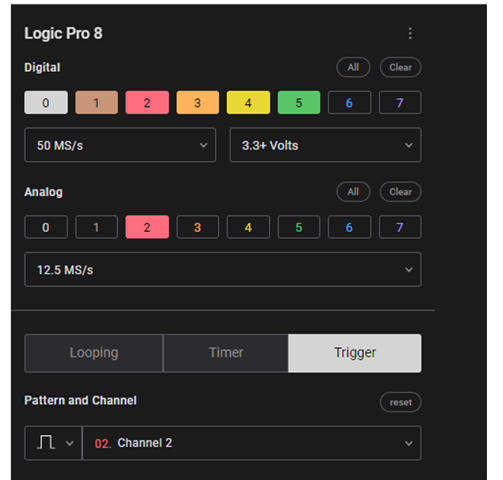
Our logical analyzer:saleae logic Pro8
The software for logical analyzer is Logic Setup 2.4.7-master.exe, and the download address is
https://www.saleae.com/downloads/
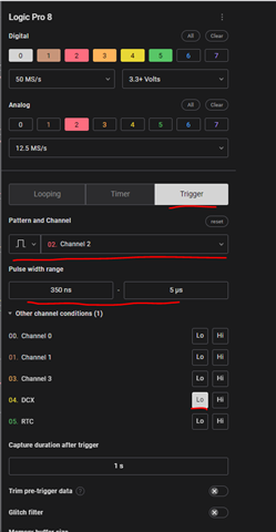
inside the logical analyzer we set the filter as below:
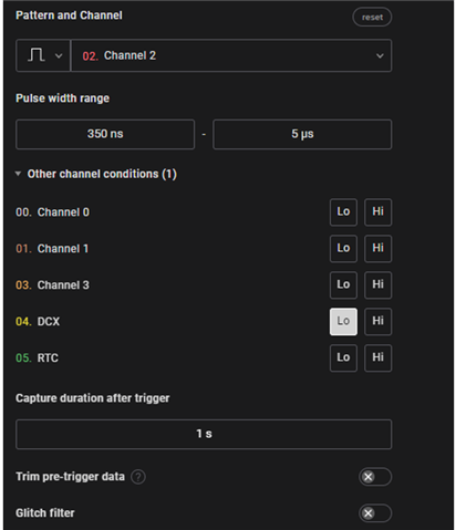
As shown in the diagram, channel 2 represents the MOSI pin. The reason for setting the pulse duration from 350us to 5us is that under normal circumstances, the pulse width of the first byte (0x2b) sent by SPIM is less than 350us, and it is triggered by a low level on DCX. If this condition is not met, it indicates that the first byte is not 0x2b, which is inconsistent with our program settings, and indicates a data transmission error.
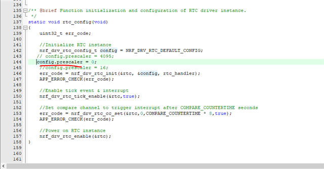
in program we setting sending data as below:
uint8_t       data6[6]	={0x2b,0xfA, 0xfC, 0xfD, 0xfE,0xf8};
    while (1)
    {
			spi_xfer_done = false;
			nrfx_spim_xfer_desc_t xfer_desc3 = NRFX_SPIM_XFER_TRX(data6, 6, NULL, 0);
			APP_ERROR_CHECK(nrfx_spim_xfer_dcx(&spi, &xfer_desc3, 0, 1));
			while (!spi_xfer_done)
			{
				//	__WFE();
			}
			nrf_delay_ms(5);
    }
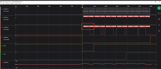
in our prject we expect the data & cmd should be send as below(the first byte for cmd is 0x2b):
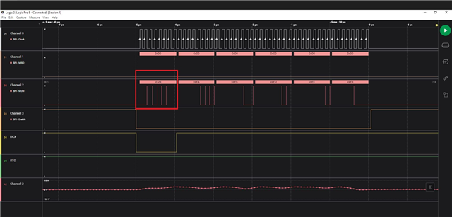
The error data could show as below:(the first byte has been change to 0xF8 ):
i also try to set SCK & MOSI gpio to H0H1, but the issue still happen.
The reproduce project: