ESB Tx current Spike issued

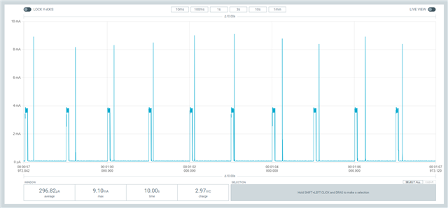
The part where the current goes up is the ESB Tx section. Why does the power consumption vary every time? I am currently using a DCDC regulator and a self-made board.

The main CPU being used is nrf52833.

ESB Tx power consumption appears differently every time, with three different values: 37mA, 5mA, and 500uA

Based on the datasheet, I believe that 5mA is the normal power consumption.

I've looked at other examples in the Q&A, but is this phenomenon that occurs with DCDC regulators a common issue?

Even when I connected 1.3V direct power from PPK to the DCDC regulator pin, the issue did not go away.

What parts should I look at?

  • Hi 

    You mean to say you use a DCDC regulator external to the nRF52833?

    I expect this to be a property of the regulator, and the connected passives (decoupling caps etc). 

    If you test the same code on a nRF52833DK I expect you will see much more consistent results. 

    Have you tried to compare the energy in each spike to see if there is a significant difference? 

    What kind of current do you get if you keep the CPU in the nRF running continuously?

    Best regards
    Torbjørn

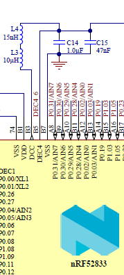
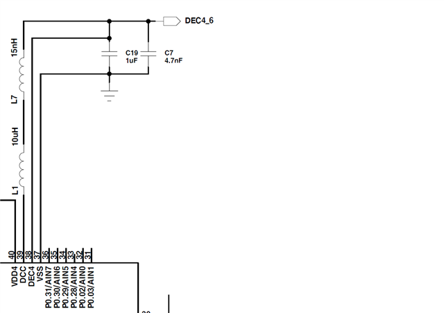
  • DK 보드와 ​​같은 레퍼런스 디자인으로 DEC4 핀에 DCDC 레귤레이터 회로를 추가했습니다.

    전원을 인가하면 DEC4핀에 1.3V의 전압이 공급된다.
    각 스파이크의 에너지를 비교할 때 전체 에너지의 총량은 크게 다르지 않습니다. 하지만 이 에너지가 항상 같으면 좋겠습니다.
    C7의 값도 4.7nF에서 47nF로 변경해 보았지만 현상은 그대로였습니다.
    "nRF에서 CPU를 계속 실행하면 어떤 종류의 전류를 얻습니까?"가 무슨 뜻인지 잘 모르겠습니다. 설명해 주시겠습니까?
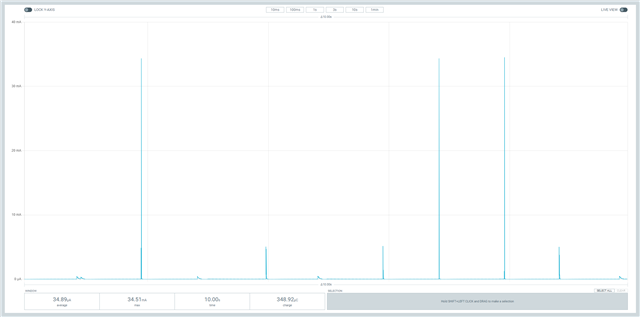
    다음 그림은 nRF52833DK 보드에서 동일한 프로그램을 실행할 때의 전력 소모를 보여줍니다.
    이전보다 더 일관된 값을 얻을 수 있었습니다.
    그러나 Tx 이전에 비정상적인 파형이 나타났습니다. 모든 LED가 꺼져 있지만 값이 무엇인지 알 수 없습니다.
  • In addition, is the abnormal ESB Tx current consumption also related to antenna matching?

Related