Short between J1 Signal pin and ground for NRF52833

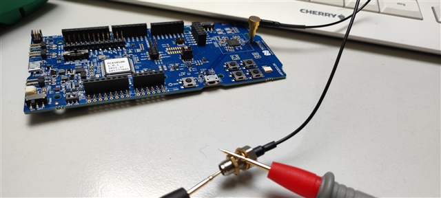
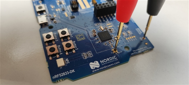
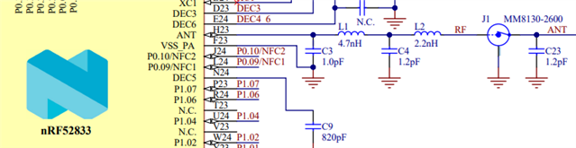
I was doing some tests with an external antenna and I noticed that the connector J1 from the NRF52833 DK has a short circuit between the J1 radio signal pin and ground. Is this normal?

I tried another board (NRF5340) and the J1 pin signal is not connected to ground.

I noticed this because I tested continuity with a multimeter between the probe cable signal pin and the ground

Parents
  • Hi

    How do you measure exactly? If you see in the nRF52833 DK HW files (and any other DK HW designs for that matter), you can see that the J1 is a switch that either is set to GND or to the ANT line.

    Why and how are you measuring the J1 pin at all? Is the DK not working correctly?

    Best regards,

    Simon

  • Sorry for the late reply. Seems that I did not see the notification.

    I was trying to do a sanity check on my part for the connection with the external antenna as I am evaluating Bluetooth AoA.


    Seems that the ANT pin (H23) is detected to be connected to GND by the multimeter for the NRF52833 DK. In the NRF5340 DK this does not happen with the multimeter. Thats the reason I was trying to ask here if thats how it works becase I see that both designs are similar.

Reply
  • Sorry for the late reply. Seems that I did not see the notification.

    I was trying to do a sanity check on my part for the connection with the external antenna as I am evaluating Bluetooth AoA.


    Seems that the ANT pin (H23) is detected to be connected to GND by the multimeter for the NRF52833 DK. In the NRF5340 DK this does not happen with the multimeter. Thats the reason I was trying to ask here if thats how it works becase I see that both designs are similar.

Children
No Data
Related