nrf9160 (MODBUS)

Good day 

Our custom board contains RS485 implementation.  The file schematic for that looks like this:

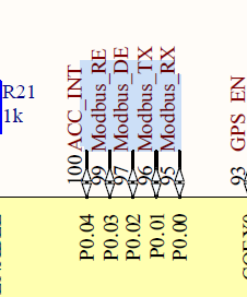
I have noticed that a driver and sample exists but the driver doesn't seem to incorporate re-gpios.  My DTS and DTSI file contains this:

 &uart0 {
    status = "okay";
    current-speed = <115200>;
    pinctrl-0 = <&uart0_default>;
    pinctrl-1 = <&uart0_sleep>;
    pinctrl-names = "default", "sleep";
    modbus0 {
        compatible = "zephyr,modbus-serial";
        status = "okay";
        de-gpios = < &gpio0 2 1>;   /* D9 */
        re-gpios = < &gpio0 3 0>;/
    };
 };
and 
uart0_default: uart0_default {
        group1 {
            psels = <NRF_PSEL(UART_TX, 0, 1)>,
                <NRF_PSEL(UART_RX, 0, 0)>;
        };
    };

    uart0_sleep: uart0_sleep {
        group1 {
            psels = <NRF_PSEL(UART_TX, 0, 1)>,
                <NRF_PSEL(UART_RX, 0, 0)>;
            low-power-enable;
        };
    };
  as i've seen that re-gpios has been included in the yaml files.  Is there a way that I can ensure that the driver(v2.2.0\zephyr\include\zephyr\modbus\modbus.h) incorporates the use of this pin?  Thank you in advance
Kind regards,
HassaN
  • Good day Hassan,

    I'm sorry for the delay, I was sick for the start of last week and then we had two national holidays following each other.

    I still have you ask you a follow-up question, sorry: What do you mean by re-gpios? I can't find any reference to this concept.

    Is your issue by any chance related to this:  RE: Modbus(RS485) communication using UART1 on Nrf9160?

    Here is another case on a customer trying to set up modbus (note my colleague's suggestions as well):  Using the nRF9160 to send and receive data over RS485 (using uart?)

    And, if it is of any help, I see that another customer has had success using this modbus library: RE: nRF9160 RS485 MODBUS 

    Best regards,

    Raoul

  • de-gpios would be drive enable-gpios,

    re-gpios would be read/receive enable-gpios.

    RS485 using two wires is half-duplex. Meaning you need a pin to switch between receiving (reading) and sending (driving) the bus. As such, there's the de-gpios node in the devicetree to specify what GPIO pin is wired to the DE-pin of the RS485 chip.

    Most RS485 chips however have two pins rather than a single one: One for enabling read, one for enabling write, because chips consume power when they're active. By being able to turn off both direction one can conserve some extra (battery) power.

    Hence it makes sense to also have a re-gpios, which enables receiving in hardware, when software is actually taking in data.

    One can do without re-gpios though: All the chips I have seen with two pins (separate drive enable & read enable) have the read enable inverted. So to activate drive, one needs drive the drive enable-pin high. But to activate reading, because it is inverted, one needs pull the read enable-pin low. This means you can connect them together on the PCB to the same GPIO.

    Having drive enable-pin and inverted read enable-pin tied together on the PCB however means the RS485 chip rests in receive mode, which eats more power than being off.

Related