I successfully installed a SX1276 with a nRF5340 and transmitted some lorawan packets to Helium Network.
After I concluded I could do the same using the nRF52840. So I installed another one module solded on dongle's pin.
In order to start this project I created the blink to know if the things were working. The led1 blinked.
After I just adjusted the .overlay and organized the pins, at same way I done using the other project.
And I put some lorawan configs on .prj.
For my surprise, the led didn't blink.
In order to test, doesn't need connect anything because the problem is only the configs.
This is the original blink project, added innocuous commands:
/*
 * Copyright (c) 2016 Intel Corporation
 *
 * SPDX-License-Identifier: Apache-2.0
 */

#include <zephyr/kernel.h>
#include <zephyr/drivers/gpio.h>

#include <zephyr/device.h>
#include <zephyr/lorawan/lorawan.h>

#include <zephyr/drivers/lora.h>

#include <soc.h>
#include <stdio.h>
#include <stdlib.h>
#include <string.h>


#include <zephyr/types.h>
#include <zephyr/kernel.h>
#include <zephyr/drivers/uart.h>

#include <zephyr/drivers/gpio.h>
#include <zephyr/drivers/adc.h>
#include <zephyr/usb/usb_device.h>


/* Customize based on network configuration */


#define LORAWAN_DEV_EUI_HELIUM  {0x60, 0x81, 0xF9, 0x44, 0x0A, 0xFD, 0x54, 0x56} //msb
#define LORAWAN_JOIN_EUI_HELIUM {0x60, 0x81, 0xF9, 0x82, 0xBD, 0x7F, 0x80, 0xD3} //msb
#define LORAWAN_APP_KEY_HELIUM  {0x40, 0xA3, 0x4B, 0x94, 0x3E, 0x86, 0xD8, 0x38, 0xC2, 0x4F, 0x36, 0xA4, 0xEC, 0xA7, 0x79, 0x03}
#define ON 1
#define OFF 0

#define DELAY K_MSEC(10000)
#define SUPER_DELAY K_MSEC(60000)

/*
#define LOG_LEVEL CONFIG_LOG_DEFAULT_LEVEL
#include <zephyr/logging/log.h>
LOG_MODULE_REGISTER(lorawan_class_a);
*/


 char data[] =        { 0X00 , 0X00 , 0X00 , 0X00 , //LATITUDE
                        0X00 , 0X00 , 0X00 , 0X00 , //LONGITUDE
					    0X00 , 0X00 , 0X00 , 0X00 , //TIMESTAMP
					    0X00 , 0X00 , 0X00 , 0X00 , //ANALOG
                        0X00 ,                      //DIGITAL
                        0X00 ,                      //DIGITAL
					    0X00 , 0X00 ,               //NTC0
                        0X00 , 0X00 ,               //NTC1
                        0X00 , 0X00                 //NTC2
                      };


/* 1000 msec = 1 sec */
#define SLEEP_TIME_MS   1000

/* The devicetree node identifier for the "led0" alias. */
#define LED0_NODE DT_ALIAS(led0)

/*
 * A build error on this line means your board is unsupported.
 * See the sample documentation for information on how to fix this.
 */
static const struct gpio_dt_spec led = GPIO_DT_SPEC_GET(LED0_NODE, gpios);


void main(void)
{
	int ret;

	if (!device_is_ready(led.port)) {
		return;
	}

	ret = gpio_pin_configure_dt(&led, GPIO_OUTPUT_ACTIVE);
	if (ret < 0) {
		return;
	}

	while (1) {
		ret = gpio_pin_toggle_dt(&led);
		if (ret < 0) {
			return;
		}
		k_msleep(SLEEP_TIME_MS);
	}
}
The .prj modified
CONFIG_LOG=y
CONFIG_MAIN_STACK_SIZE=2048
CONFIG_SYSTEM_WORKQUEUE_STACK_SIZE=2048

CONFIG_SPI=y

CONFIG_LORA=y

CONFIG_LORA_SX12XX=y
CONFIG_LORA_SX127X=y
CONFIG_LORAWAN=y
CONFIG_LORAMAC_REGION_EU868=y
CONFIG_LORA_LOG_LEVEL_DBG=y
CONFIG_HAS_SEMTECH_RADIO_DRIVERS=y
This is the Overlay's file created on example Blink Project
&spi1 {
    //VDD - CONNECT TO 3V - USE A 220UF TO GND
    //SCK  -->P1.15
	//MISO -->P1.10
    //MOSI -->P1.13
    cs-gpios = <&gpio0 2 GPIO_ACTIVE_LOW>; // PIN NSS
    lora0: sx1276@0 {
		        compatible = "semtech,sx1276";
		        reset-gpios = <&gpio0 29 GPIO_ACTIVE_LOW>; //RESET PIN
		        dio-gpios =
                 <&gpio0 15 (GPIO_PULL_DOWN | GPIO_ACTIVE_HIGH)>, //DIO-0
                 <&gpio0 13 (GPIO_PULL_DOWN | GPIO_ACTIVE_HIGH)>; //DIO-1

		        power-amplifier-output = "pa-boost";
		        reg = <0>;
		        spi-max-frequency = <1000000>;
		        //label = "sx1276";
          };

};

&pinctrl{
    spi1_default: spi1_default {
		group1 {
			psels = <NRF_PSEL(SPIM_SCK, 1, 15)>,
				<NRF_PSEL(SPIM_MOSI, 1, 13)>,
				<NRF_PSEL(SPIM_MISO, 1, 10)>;
		};
	};

	spi1_sleep: spi1_sleep {
		group1 {
			psels = <NRF_PSEL(SPIM_SCK, 1, 15)>,
				<NRF_PSEL(SPIM_MOSI, 1, 13)>,
				<NRF_PSEL(SPIM_MISO, 1, 10)>;
			low-power-enable;
		};
	};


};
/ {
    aliases {
        lora = &lora0;
    };
};
Generated .HEX file ok.
[167/172] Generating linker.cmd
[168/172] Generating isr_tables.c, isrList.bin
[169/172] Building C object zephyr/CMakeFiles/zephyr_final.dir/misc/empty_file.c.obj
[170/172] Building C object zephyr/CMakeFiles/zephyr_final.dir/dev_handles.c.obj
[171/172] Building C object zephyr/CMakeFiles/zephyr_final.dir/isr_tables.c.obj
[172/172] Linking C executable zephyr\zephyr.elf
Memory region         Used Size  Region Size  %age Used
           FLASH:       66036 B      1020 KB      6.32%
             RAM:       16128 B       256 KB      6.15%
        IDT_LIST:          0 GB         2 KB      0.00%
Then I upload the code to NRF52840 Dongle using the Programmer 3.0.8.
Resulted, the led1 doesn't blink.
But, if I comment the .prj as below:
CONFIG_LOG=y
CONFIG_MAIN_STACK_SIZE=2048
CONFIG_SYSTEM_WORKQUEUE_STACK_SIZE=2048

CONFIG_SPI=y
CONFIG_LORA=y

#CONFIG_LORA_SX12XX=y
#CONFIG_LORA_SX127X=y
#CONFIG_LORAWAN=y
#CONFIG_LORAMAC_REGION_EU868=y
#CONFIG_LORA_LOG_LEVEL_DBG=y
#CONFIG_HAS_SEMTECH_RADIO_DRIVERS=y
The led1 start blinking.
Does anyone can explain why?
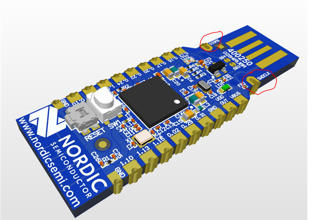
The dongle doesn't have SWD to connect, I can't see any RTT messages.
The same .prj works perfectly on NRF5340DK.
Thanks in advance.