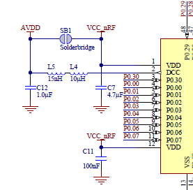
Referring to the PCA10001 schematic, there is a solder bridge SB1, which connects AVDD with VCC_nRF.
Can you please explain in which cases is it needed?
Thank you Oleh

Referring to the PCA10001 schematic, there is a solder bridge SB1, which connects AVDD with VCC_nRF.
Can you please explain in which cases is it needed?
Thank you Oleh

Hi,
For LDO operation: There's an internal coupling between VDD and AVDD, so that solder bridge does need to be shorted. However, the internal switch will add a series-resistance, so shorting SB1 it will lead to a lower resistance.
For DCDC operation: Then there should not be a wired connection between AVDD and VDD, as AVDD will have another level than VDD.
Best regards Håkon
Hi again Oleh,
By connecting VDD and AVDD together while in DCDC operation, you will bypass the DCDC in effect and may damage the chip. This will not work (double checked with HW-designer).
What you should do is use the reference design w/DCDC (figure 16 in the PS v2.0). This will also work with LDO operation, as there is an internal switch from VCC_NRF to AVDD. The chip will start up on normal LDO until you enable the DCDC in your firmware.
If you are to connected VCC_NRF and AVDD, you just remove the components on "DCC" pin (ie: run nRF on normal LDO operation power scheme).
Best regards Håkon