PWM via IR nRF5340

Hi,

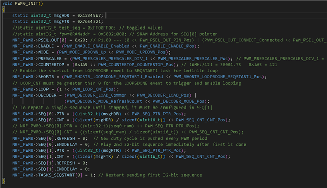
I'm attempting to transmit IR signals over one of the PWM channels on the nRF5340. I noticed that the PRESCALER register only has 0 - 7 values in the OPS reference manual even though it's a 32-bit register. Is it possible to configure the 16MHz clock to be 38kHz for IR?

Thanks!

Brad

Parents
  • Hi,

    Other values are not supported. (Only the lower 3 bits of the register are in use).

  • Hi Einar,

    Would the nRF5340 be able to do IR transmission through one of the other peripherals instead?

    Thanks,

    Brad

  • Hi Brad,

    There are several ways to generate PWM signals from the nRF, but I would prefer the PWM peripheral in this case. This has some nice features, particularily that it can play out a sequence via DMA, so very little CPU intervention is needed. Note that the frequency does not only depend on the PRESCALER, and can be much lower than the lowest frequency out of the prescaler, where there may have been a misunderstanding. I suggest you take a look at the PWM chapter in the PS while playing with the PWM examples under modules/hal/nordic/nrfx/samples/src/nrfx_pwm/. If you hook the output to a logic analyzer and play with it a bit, you can more easily get an understanding of how this PWM peripheral works (it is unfortunately a bit complicated, but also quite flexible).

    If you for some reason don't want to use the PWM peripheral, an alternative is to connect a timer to GPIOTE via PPI to get a pin toggling at a specific frequency, but then you would need SW every time you need to change the duty cycle or do other changes. (This can be done by using "sw_pwm" with Zephyr, where a SW library using the mentioned approach generates the PWM signal).

    Einar

  • Hi Einar,

    So I've set the PWM0 Peripheral like so:

    But I'm only getting transitions on P0.01, P0.11, and P0.28? I figured the above code would set the P0.20 pin as the PWM0 output. Here is what I'm seeing on P0.01:

    This is P0.11:

    And this is P0.28:

    I'm not sure if my code is setting up the channel incorrectly.

Reply Children
  • For more context, I'm trying to send the 1st and 2nd sequences as one 64-bit (2, 32-bit messages) transmission infinitely.

  • Hi Brad,

    You write that you want to output on P0.20, but you write 0x20 (which is 32 = P1.00) to PSEL.OUT. So it is expected that you do not see any output on P0.20. I do not see how P0.01, P0.11 and P0.28 are related to this though?

    Also, I would generally recommend using the nrfx driver (as demonstrated in the examples mentioned in my previous post), as that is typically less time consuming and less error-prone than doing the low-level stuff yourself. 

    PS: Please consider adding code via Insert -> Code instead of screenshots, to make it easier to search, copy-paste etc.

    Einar

  • Hi Einar,

    I mistyped. If you look at my code I know that 0x20 sets P1.00 (in the comments). Why does my code below not output anything on P1.00?

    void PWM0_INIT()
    {
    	// static uint32_t *pwm0RAMaddr = 0x50021000; // SRAM Address for SEQ[0] pointer
    	NRF_PWM0->PSEL.OUT[0] = (0 << PWM_PSEL_OUT_PIN_Pos) | (PWM_PSEL_OUT_CONNECT_Connected << PWM_PSEL_OUT_CONNECT_Pos); // replaced first_pin with 0
    	NRF_PWM0->ENABLE = (PWM_ENABLE_ENABLE_Enabled << PWM_ENABLE_ENABLE_Pos);
    	NRF_PWM0->MODE = (PWM_MODE_UPDOWN_Up << PWM_MODE_UPDOWN_Pos);
    	NRF_PWM0->PRESCALER = (PWM_PRESCALER_PRESCALER_DIV_1 << PWM_PRESCALER_PRESCALER_Pos); // PWM_PRESCALER_PRESCALER_DIV_1 =
    	NRF_PWM0->COUNTERTOP = (0x1A5 << PWM_COUNTERTOP_COUNTERTOP_Pos);					  // 16MHz/421 = 38004.75   0x1A5 = 421
    	// Enable the shortcut from LOOPSDONE event to SEQSTART1 task for infinite loop
    	NRF_PWM0->SHORTS = (PWM_SHORTS_LOOPSDONE_SEQSTART1_Enabled << PWM_SHORTS_LOOPSDONE_SEQSTART1_Pos);
    	// LOOP_CNT must be greater than 0 for the LOOPSDONE event to trigger and enable looping
    	NRF_PWM0->LOOP = (1 << PWM_LOOP_CNT_Pos);
    	NRF_PWM0->DECODER = (PWM_DECODER_LOAD_Common << PWM_DECODER_LOAD_Pos) |
    						(PWM_DECODER_MODE_RefreshCount << PWM_DECODER_MODE_Pos);
    	// To repeat a single sequence until stopped, it must be configured in SEQ[1]
    	NRF_PWM0->SEQ[0].PTR = (msgHDR << PWM_SEQ_PTR_PTR_Pos);
    	NRF_PWM0->SEQ[0].CNT = ((sizeof(msgHDR) / sizeof(uint16_t)) << PWM_SEQ_CNT_CNT_Pos);
    	// NRF_PWM0->SEQ[0].PTR = ((uint32_t)(seq0_ram) << PWM_SEQ_PTR_PTR_Pos);
    	// NRF_PWM0->SEQ[0].CNT = ((sizeof(seq0_ram) / sizeof(uint16_t)) << PWM_SEQ_CNT_CNT_Pos);
    	NRF_PWM0->SEQ[0].REFRESH = 0;  // New duty cycle is pushed every PWM period
    	NRF_PWM0->SEQ[0].ENDDELAY = 0; // Play 2nd 32-bit sequence immediately after first is done
    	NRF_PWM0->SEQ[1].PTR = (msgFTR << PWM_SEQ_PTR_PTR_Pos);
    	NRF_PWM0->SEQ[1].CNT = ((sizeof(msgFTR) / sizeof(uint16_t)) << PWM_SEQ_CNT_CNT_Pos);
    	NRF_PWM0->SEQ[1].REFRESH = 10;
    	NRF_PWM0->SEQ[1].ENDDELAY = 10;
    	NRF_PWM0->TASKS_SEQSTART[0] = 1; // Restart sending first 32-bit sequence
    }

  • My LogicAnalyzer just shows that the pin is held high forever:

  • Sorry here is the correct version of code that is currently flashed on the board

    void PWM0_INIT()
    {	
    	static uint32_t msgHDR = 0x1234567; 
    	static uint32_t msgFTR = 0x7654321;	 
    	//static uint32_t test_seq = 0xFF00FF00; // toggled values
    	//static uint32_t *pwm0RAMaddr = 0x50021000; // SRAM Address for SEQ[0] pointer
    	NRF_PWM0->PSEL.OUT[0] = 0x20; // P1.00 --- (0 << PWM_PSEL_OUT_PIN_Pos) | (PWM_PSEL_OUT_CONNECT_Connected << PWM_PSEL_OUT_CONNECT_Pos); // replaced first_pin with 0
    	NRF_PWM0->ENABLE = (PWM_ENABLE_ENABLE_Enabled << PWM_ENABLE_ENABLE_Pos);
    	NRF_PWM0->MODE = (PWM_MODE_UPDOWN_Up << PWM_MODE_UPDOWN_Pos);
    	NRF_PWM0->PRESCALER = (PWM_PRESCALER_PRESCALER_DIV_1 << PWM_PRESCALER_PRESCALER_Pos); // PWM_PRESCALER_PRESCALER_DIV_1 =
    	NRF_PWM0->COUNTERTOP = (0x1A5 << PWM_COUNTERTOP_COUNTERTOP_Pos); // 16MHz/421 = 38004.75   0x1A5 = 421
    	// Enable the shortcut from LOOPSDONE event to SEQSTART1 task for infinite loop
    	NRF_PWM0->SHORTS = (PWM_SHORTS_LOOPSDONE_SEQSTART1_Enabled << PWM_SHORTS_LOOPSDONE_SEQSTART1_Pos);
    	// LOOP_CNT must be greater than 0 for the LOOPSDONE event to trigger and enable looping
    	NRF_PWM0->LOOP = (1 << PWM_LOOP_CNT_Pos);
    	NRF_PWM0->DECODER = (PWM_DECODER_LOAD_Common << PWM_DECODER_LOAD_Pos) |
    						(PWM_DECODER_MODE_RefreshCount << PWM_DECODER_MODE_Pos);
    	// To repeat a single sequence until stopped, it must be configured in SEQ[1]
    	NRF_PWM0->SEQ[0].PTR = ((uint32_t)(msgHDR) << PWM_SEQ_PTR_PTR_Pos);
    	NRF_PWM0->SEQ[0].CNT = ((sizeof(msgHDR) / sizeof(uint16_t)) << PWM_SEQ_CNT_CNT_Pos);
    	// NRF_PWM0->SEQ[0].PTR = ((uint32_t)(seq0_ram) << PWM_SEQ_PTR_PTR_Pos);
    	// NRF_PWM0->SEQ[0].CNT = ((sizeof(seq0_ram) / sizeof(uint16_t)) << PWM_SEQ_CNT_CNT_Pos);
    	NRF_PWM0->SEQ[0].REFRESH = 0;  // New duty cycle is pushed every PWM period
    	NRF_PWM0->SEQ[0].ENDDELAY = 0; // Play 2nd 32-bit sequence immediately after first is done
    	NRF_PWM0->SEQ[1].PTR = ((uint32_t)(msgFTR) << PWM_SEQ_PTR_PTR_Pos);
    	NRF_PWM0->SEQ[1].CNT = ((sizeof(msgFTR) / sizeof(uint16_t)) << PWM_SEQ_CNT_CNT_Pos);
    	NRF_PWM0->SEQ[1].REFRESH = 0;
    	NRF_PWM0->SEQ[1].ENDDELAY = 0;
    	NRF_PWM0->TASKS_SEQSTART[0] = 1; // Restart sending first 32-bit sequence
    }

Related