PWM via IR nRF5340

Hi,

I'm attempting to transmit IR signals over one of the PWM channels on the nRF5340. I noticed that the PRESCALER register only has 0 - 7 values in the OPS reference manual even though it's a 32-bit register. Is it possible to configure the 16MHz clock to be 38kHz for IR?

Thanks!

Brad

  • For more context, I'm trying to send the 1st and 2nd sequences as one 64-bit (2, 32-bit messages) transmission infinitely.

  • Hi Brad,

    You write that you want to output on P0.20, but you write 0x20 (which is 32 = P1.00) to PSEL.OUT. So it is expected that you do not see any output on P0.20. I do not see how P0.01, P0.11 and P0.28 are related to this though?

    Also, I would generally recommend using the nrfx driver (as demonstrated in the examples mentioned in my previous post), as that is typically less time consuming and less error-prone than doing the low-level stuff yourself. 

    PS: Please consider adding code via Insert -> Code instead of screenshots, to make it easier to search, copy-paste etc.

    Einar

  • Hi Einar,

    I mistyped. If you look at my code I know that 0x20 sets P1.00 (in the comments). Why does my code below not output anything on P1.00?

    void PWM0_INIT()
    {
    	// static uint32_t *pwm0RAMaddr = 0x50021000; // SRAM Address for SEQ[0] pointer
    	NRF_PWM0->PSEL.OUT[0] = (0 << PWM_PSEL_OUT_PIN_Pos) | (PWM_PSEL_OUT_CONNECT_Connected << PWM_PSEL_OUT_CONNECT_Pos); // replaced first_pin with 0
    	NRF_PWM0->ENABLE = (PWM_ENABLE_ENABLE_Enabled << PWM_ENABLE_ENABLE_Pos);
    	NRF_PWM0->MODE = (PWM_MODE_UPDOWN_Up << PWM_MODE_UPDOWN_Pos);
    	NRF_PWM0->PRESCALER = (PWM_PRESCALER_PRESCALER_DIV_1 << PWM_PRESCALER_PRESCALER_Pos); // PWM_PRESCALER_PRESCALER_DIV_1 =
    	NRF_PWM0->COUNTERTOP = (0x1A5 << PWM_COUNTERTOP_COUNTERTOP_Pos);					  // 16MHz/421 = 38004.75   0x1A5 = 421
    	// Enable the shortcut from LOOPSDONE event to SEQSTART1 task for infinite loop
    	NRF_PWM0->SHORTS = (PWM_SHORTS_LOOPSDONE_SEQSTART1_Enabled << PWM_SHORTS_LOOPSDONE_SEQSTART1_Pos);
    	// LOOP_CNT must be greater than 0 for the LOOPSDONE event to trigger and enable looping
    	NRF_PWM0->LOOP = (1 << PWM_LOOP_CNT_Pos);
    	NRF_PWM0->DECODER = (PWM_DECODER_LOAD_Common << PWM_DECODER_LOAD_Pos) |
    						(PWM_DECODER_MODE_RefreshCount << PWM_DECODER_MODE_Pos);
    	// To repeat a single sequence until stopped, it must be configured in SEQ[1]
    	NRF_PWM0->SEQ[0].PTR = (msgHDR << PWM_SEQ_PTR_PTR_Pos);
    	NRF_PWM0->SEQ[0].CNT = ((sizeof(msgHDR) / sizeof(uint16_t)) << PWM_SEQ_CNT_CNT_Pos);
    	// NRF_PWM0->SEQ[0].PTR = ((uint32_t)(seq0_ram) << PWM_SEQ_PTR_PTR_Pos);
    	// NRF_PWM0->SEQ[0].CNT = ((sizeof(seq0_ram) / sizeof(uint16_t)) << PWM_SEQ_CNT_CNT_Pos);
    	NRF_PWM0->SEQ[0].REFRESH = 0;  // New duty cycle is pushed every PWM period
    	NRF_PWM0->SEQ[0].ENDDELAY = 0; // Play 2nd 32-bit sequence immediately after first is done
    	NRF_PWM0->SEQ[1].PTR = (msgFTR << PWM_SEQ_PTR_PTR_Pos);
    	NRF_PWM0->SEQ[1].CNT = ((sizeof(msgFTR) / sizeof(uint16_t)) << PWM_SEQ_CNT_CNT_Pos);
    	NRF_PWM0->SEQ[1].REFRESH = 10;
    	NRF_PWM0->SEQ[1].ENDDELAY = 10;
    	NRF_PWM0->TASKS_SEQSTART[0] = 1; // Restart sending first 32-bit sequence
    }

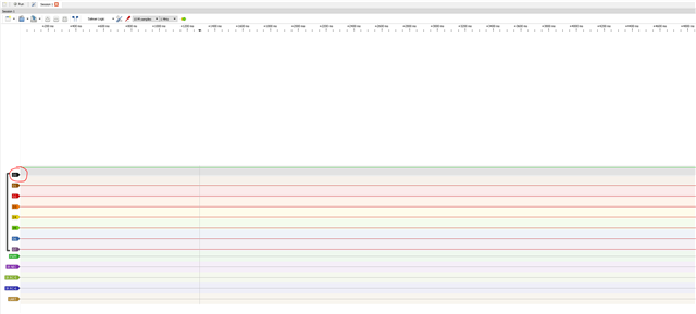
  • My LogicAnalyzer just shows that the pin is held high forever:

  • Sorry here is the correct version of code that is currently flashed on the board

    void PWM0_INIT()
    {	
    	static uint32_t msgHDR = 0x1234567; 
    	static uint32_t msgFTR = 0x7654321;	 
    	//static uint32_t test_seq = 0xFF00FF00; // toggled values
    	//static uint32_t *pwm0RAMaddr = 0x50021000; // SRAM Address for SEQ[0] pointer
    	NRF_PWM0->PSEL.OUT[0] = 0x20; // P1.00 --- (0 << PWM_PSEL_OUT_PIN_Pos) | (PWM_PSEL_OUT_CONNECT_Connected << PWM_PSEL_OUT_CONNECT_Pos); // replaced first_pin with 0
    	NRF_PWM0->ENABLE = (PWM_ENABLE_ENABLE_Enabled << PWM_ENABLE_ENABLE_Pos);
    	NRF_PWM0->MODE = (PWM_MODE_UPDOWN_Up << PWM_MODE_UPDOWN_Pos);
    	NRF_PWM0->PRESCALER = (PWM_PRESCALER_PRESCALER_DIV_1 << PWM_PRESCALER_PRESCALER_Pos); // PWM_PRESCALER_PRESCALER_DIV_1 =
    	NRF_PWM0->COUNTERTOP = (0x1A5 << PWM_COUNTERTOP_COUNTERTOP_Pos); // 16MHz/421 = 38004.75   0x1A5 = 421
    	// Enable the shortcut from LOOPSDONE event to SEQSTART1 task for infinite loop
    	NRF_PWM0->SHORTS = (PWM_SHORTS_LOOPSDONE_SEQSTART1_Enabled << PWM_SHORTS_LOOPSDONE_SEQSTART1_Pos);
    	// LOOP_CNT must be greater than 0 for the LOOPSDONE event to trigger and enable looping
    	NRF_PWM0->LOOP = (1 << PWM_LOOP_CNT_Pos);
    	NRF_PWM0->DECODER = (PWM_DECODER_LOAD_Common << PWM_DECODER_LOAD_Pos) |
    						(PWM_DECODER_MODE_RefreshCount << PWM_DECODER_MODE_Pos);
    	// To repeat a single sequence until stopped, it must be configured in SEQ[1]
    	NRF_PWM0->SEQ[0].PTR = ((uint32_t)(msgHDR) << PWM_SEQ_PTR_PTR_Pos);
    	NRF_PWM0->SEQ[0].CNT = ((sizeof(msgHDR) / sizeof(uint16_t)) << PWM_SEQ_CNT_CNT_Pos);
    	// NRF_PWM0->SEQ[0].PTR = ((uint32_t)(seq0_ram) << PWM_SEQ_PTR_PTR_Pos);
    	// NRF_PWM0->SEQ[0].CNT = ((sizeof(seq0_ram) / sizeof(uint16_t)) << PWM_SEQ_CNT_CNT_Pos);
    	NRF_PWM0->SEQ[0].REFRESH = 0;  // New duty cycle is pushed every PWM period
    	NRF_PWM0->SEQ[0].ENDDELAY = 0; // Play 2nd 32-bit sequence immediately after first is done
    	NRF_PWM0->SEQ[1].PTR = ((uint32_t)(msgFTR) << PWM_SEQ_PTR_PTR_Pos);
    	NRF_PWM0->SEQ[1].CNT = ((sizeof(msgFTR) / sizeof(uint16_t)) << PWM_SEQ_CNT_CNT_Pos);
    	NRF_PWM0->SEQ[1].REFRESH = 0;
    	NRF_PWM0->SEQ[1].ENDDELAY = 0;
    	NRF_PWM0->TASKS_SEQSTART[0] = 1; // Restart sending first 32-bit sequence
    }

Related