UART Pin Change with DTS Overlay

Hi,

I am trying to change the pins used from UART from the default pins TX:6, RX:8 to TX:9, RX:10

I am struggling to figure out how to do this as whenever I update my .overlay file for my device tree I go from a working UART implementation to seeing no data pass between the devices.

Here is the DTS code I am using to make this pin change:

// &pinctrl {
//     uart0_default: uart0_default {
//         group1 {
//             psels = <NRF_PSEL(UART_TX, 0, 9)>,
//                     <NRF_PSEL(UART_RX, 0, 10)>;
//         };
//     };
//     /* required if CONFIG_PM_DEVICE=y */
//     uart0_sleep: uart0_sleep {
//         group1 {
//             psels = <NRF_PSEL(UART_TX, 0, 9)>,
//                     <NRF_PSEL(UART_RX, 0, 10)>;
//             low-power-enable;
//         };
//     };
// };

Is there something I am missing here?

Here is what the device GUI looks like before and after the change-

Before (UART works correctly):

After (UART not working):
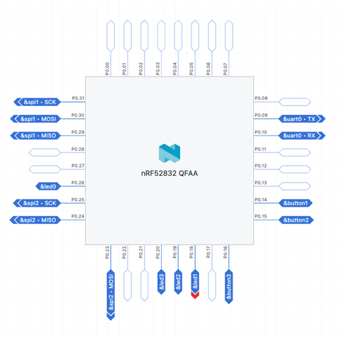
Thanks!

  • Hi Evan,

    The overlay that you have shared looks correct. Could you check if uart0 has been defined in any other group within the dts file.?

    Regards,

    Swathy

  • Hi,

    the pins for UART zero were assigned by default in the app-pinctrl.dtsi file as shown below

    &pinctrl {
    	uart0_default: uart0_default {
    		group1 {
    			psels = <NRF_PSEL(UART_TX, 0, 6)>,
    				<NRF_PSEL(UART_RX, 0, 8)>,
    				<NRF_PSEL(UART_RTS, 0, 5)>,
    				<NRF_PSEL(UART_CTS, 0, 7)>;
    		};
    	};
    
    	uart0_sleep: uart0_sleep {
    		group1 {
    			psels = <NRF_PSEL(UART_TX, 0, 6)>,
    				<NRF_PSEL(UART_RX, 0, 8)>,
    				<NRF_PSEL(UART_RTS, 0, 5)>,
    				<NRF_PSEL(UART_CTS, 0, 7)>;
    			low-power-enable;
    		};
    	};

    This being said, these lines are faded becuase they are being overriden by the lines in my overlay file described above. I have also tried changing these lines directly without using an overlay and I encounter the same issue.

    The only other place uart0 is defined is in the app.dts file but these line referece the pin control file to declare the pins as seen below:

    arduino_serial: &uart0 {
    	status = "okay";
    	compatible = "nordic,nrf-uarte";
    	current-speed = <115200>;
    	pinctrl-0 = <&uart0_default>;
    	pinctrl-1 = <&uart0_sleep>;
    	pinctrl-names = "default", "sleep";
    };

    Let me know if I can provide any more info that my be relevant to this.

    Thanks!

  • Hi Evan,

    How are you checking the outputs.? Did you use a logic analyzer to check the UART outputs after changing the pins.? By not working, is there any error message that shows up or only that the expected output does not appear in the newly assigned pins..? The overlay looks correct and I cannot see why this is not working.

    Regards,

    Swathy

  • Hi Swathy,

    I am using a serial to USB cable outputting to a standard serial terminal (screen or Arduino). I do not see any errors with either version of the DTS file but when I use the default pins I am able to send and receive serial data and when I use my modified pins I am not so as you stated 'the expected output does not appear in the newly assigned pins'. Again the code is not logging any errors. I will experiment with this a little more later today to see if I can give you any more specific information.

  • Hi Evan,

    Are you using the 52-DK.? If you see the backside of the board, you can see the pins that are already in use.. So could you try with any other free gpio.?

    Regards,

    Swathy

Related