Correct calibration of the nRF51 ADC to correct offset and gain error

Hello,

a follow-up/corresponding question to this topic:
https://devzone.nordicsemi.com/f/nordic-q-a/4517/how-to-calibrate-the-nrf51-adc-to-correct-offset-and-gain-error/426557

after this thread is already 8 years old, have there been some changes with offset and gain error calculations?
Does ADC already work with the stored error values automatically or does it still be have to be applied manually?
This is a question for both nrF51802 and nrF51822 devices.

I am asking this because measurement seems to be more accurate if the errors are not calibrated to the measurement calculation.

for explanation:

I have a signal to be measured, it is in the range of 10-30mV. Depends a little bit on the PCBA and components used,
as we are measuring the voltage drop across a MOSFET device. We apply 1A to the output and measure the Voltage
across the MOSFET (same goes for a measurement of a voltage drop over a resistor).

So if I use our FLUKE TRMS, I can read values of ~23-24mV on the PCB Testpoints.

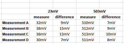
A) Now if I use this code to measure the voltage, it gets me a value of ~32mV. (already tried to implement a TRMS calculation)

note: "1.171875" is the calculated value of the ADC to mV conversion (1200/1024). the voltages are measured, calculated,
squared (voltage_squared) and summed until the "SAMPLES_IN_BUFFER" value is reached - in this case 20. Then the sum (sum_squares)
is divided through the amount of samples taken (SAMPLES_IN_BUFFER) and from this value the square root is calculated:

void get_fetstate_voltage(void)
{
	 U_STATE = 0;
	 float voltage = 0;
	 float sum_squares = 0;
	 float voltage_squared = 0;
	 float mean_squares = 0;

for (int i = 0; i < SAMPLES_IN_BUFFER; i++) {
	nrf_delay_ms(1);
	nrf_drv_adc_sample_convert(&ADC_U_STATE, &adc_buffer[i]);
	voltage = adc_buffer[i] * 1.171875;
	voltage_squared = voltage * voltage;
	sum_squares += voltage_squared;
}

mean_squares = sum_squares / SAMPLES_IN_BUFFER;
U_STATE = sqrt(mean_squares);


B) If I use this code it gets me this value: 38mV
now this is basically the same code, only with additional gain & offset error calculation

note: here I have implemented the code shown here from 27.10.2015, I have also read out the code via nrfprogj,
same values - so it seems to be correct. Values from memory address show 0x10000024: FFFF0105 (GAIN=1, OFFSET=5). 
ADC_RES_10BIT = 1024.

void get_fetstate_voltage(void)
{
	 U_STATE = 0;
	 float voltage = 0;
	 float sum_squares = 0;
	 float voltage_squared = 0;
	 float mean_squares = 0;

	 static uint32_t ficr_value_32;
	 static int8_t offset_error;
	 static int8_t gain_error;

	 ficr_value_32 = *(uint32_t*)0x10000024;
	 offset_error = ficr_value_32;
	 gain_error = ficr_value_32 >> 8;


for (int i = 0; i < SAMPLES_IN_BUFFER; i++) {
	nrf_delay_ms(1);
	nrf_drv_adc_sample_convert(&ADC_U_STATE, &adc_buffer[i]);
	voltage = adc_buffer[i] * (ADC_RES_10BIT + gain_error) / ADC_RES_10BIT + offset_error - 0.5;
	voltage = voltage * 1.171875;
	voltage_squared = voltage * voltage;
	sum_squares += voltage_squared;

}
    mean_squares = sum_squares / SAMPLES_IN_BUFFER;
    U_STATE = sqrt(mean_squares);

}

 
C) If I use a standard code to read the ADC (no TRMS), I get this value: 36mV (with gain/offset error calculation)

void get_fetstate_voltage(void)
{
	 U_STATE = 0;
	 float voltage = 0;

	 static uint32_t ficr_value_32;
	 static int8_t offset_error;
	 static int8_t gain_error;

	 ficr_value_32 = *(uint32_t*)0x10000024;
	 offset_error = ficr_value_32;
	 gain_error = ficr_value_32 >> 8;

				
	 nrf_drv_adc_sample_convert(&ADC_U_STATE,  &adc_buffer[0]);  // get HE current
  
 	 U_STATE = adc_buffer[0] * (ADC_RES_10BIT + gain_error) / ADC_RES_10BIT + offset_error - 0.5;
	 U_STATE = U_STATE * 1.171875;
}


D) If I use the most simple code for this, I get this value: 30mV (no gain/offset error calculation)

void get_fetstate_voltage(void)
{
	 U_STATE = 0;
	 float voltage = 0;

	 nrf_drv_adc_sample_convert(&ADC_U_STATE,  &adc_buffer[0]);
	 U_STATE = adc_buffer[0] * 1.171875;
}


So it looks like the gain and offset error calibration somehow fails on my side, I am not sure why,
but measurement A) is taken without error calibration and is more accurate then measurement B)
also measurement D) (no error calibration) is more accurate then measurement C)

****************************************************************************************************************

If I do the same examples with a different PCB (and a different nrf51802 device):
mem read shows 0x10000024: FFFF0001 ((GAIN=0, OFFSET=1),

FLUKE TRMS = ~22mV

Measurement A) = 25mV
Measurement B) = 26mV
Measurement C) = 24mV
Measurement D) = 23mV

same on this measurement, with error calibration the output seems to have more error then without.
Could someone please have a look into this, am i somehow calibrating additional error to my measurement?

Thanks, Philip

Parents
  • Hi,

    I agree that, ideally the ADC result should be closer to the real value with calibration than without.

    Did you use TRMS so that it would be comparable with the measurement from your Fluke device?

    Could you share your initialization routine of the ADC?

    regards

    Jared 

  • Hi,

    Yes, I tried to implement TRMS measurement to get better results, to be closer to the values measured by our FLUKE device. Because I use it as reference, the closer I get with my ADC measurement the better.

    Sure, here is my code:

    Setting ADC INPUT 3 on P0.02

    #define ADC_U_STATE_PIN        		NRF_ADC_CONFIG_INPUT_3     // AIN 3 P0.02


    Defining DEFAULT CHANNEL
    static nrf_drv_adc_channel_t     ADC_U_STATE             = NRF_DRV_ADC_DEFAULT_CHANNEL(ADC_U_STATE_PIN);             // Channel instance. Default configuration used


    Which corresponds to this code (Set 10bit, full scale, ref_vbg)
    #define NRF_DRV_ADC_DEFAULT_CHANNEL(analog_input)          \
    {{{                                                       \
        .resolution = NRF_ADC_CONFIG_RES_10BIT,                \
        .input      = NRF_ADC_CONFIG_SCALING_INPUT_FULL_SCALE, \
        .reference  = NRF_ADC_CONFIG_REF_VBG,                  \
        .ain        = (analog_input)                           \
     }}, NULL}


    regards,
    Philip

  • Hi Philip,

    That looks correct,

    Do you see the same if you try to measure a set voltage from a bench top supply? What if you increase the voltage that you measure, does it become more accurate after applying the calibration then?

    regards

    Jared 

  • Hi Jared,

    thats good at least Slight smile

    If I am measuring a higher voltage (in system, WITH NO bench top supply):

    OK, if I try to measure a Voltage at ~500mV I get the following results:
    (Taken with the 0x10000024: FFFF0105 (GAIN=1, OFFSET=5) - device)

    FLUKE TRMS = ~485mV

    Measurement A) = 492mV (DIFF.=7mV)
    Measurement B) = 495mV (DIFF.=10mV)
    Measurement C) = 494mV (DIFF.=9mV)
    Measurement D) = 492mV (DIFF.=7mV)

    Error seems to get a little less, but still, with error calibration in code the measurements has the most error.


    If I do this measurement with the 0x10000024: FFFF0001 ((GAIN=0, OFFSET=1) - device:

    FLUKE TRMS = ~485mV

    Measurement A) = 486mV (DIFF.=1mV)
    Measurement B) = 487mV (DIFF.=2mV)
    Measurement C) = 487mV (DIFF.=2mV)
    Measurement D) = 486mV (DIFF.=1mV)

    Again, the device with less error written to 0x10000024 is the more accurate one, doesn't change
    if error calibration is used in code, also it doesn't really matter if TRMS measurement is done
    or not (software-wise).


    If I am measuring a higher voltage (in system, WITH bench top supply):

    OK, if I try to measure a Voltage at 500mV by bench top supply I get the following results:
    (Taken with the 0x10000024: FFFF0105 (GAIN=1, OFFSET=5) - device)

    FLUKE TRMS = ~503mV

    Measurement A) = 510mV (DIFF.=7mV)
    Measurement B) = 512mV (DIFF.=9mV)
    Measurement C) = 513mV (DIFF.=10mV)
    Measurement D) = 511mV (DIFF.=7mV)


    If I do this measurement with the 0x10000024: FFFF0001 ((GAIN=0, OFFSET=1) - device:

    FLUKE TRMS = ~503mV

    Measurement A) = 505mV (DIFF.=2mV)
    Measurement B) = 506mV (DIFF.=3mV)
    Measurement C) = 506mV (DIFF.=3mV)
    Measurement D) = 505mV (DIFF.=2mV)

  • Hi,

    PhilipSTT said:


    If I am measuring a higher voltage (in system, WITH NO bench top supply):

    OK, if I try to measure a Voltage at ~500mV I get the following results:
    (Taken with the 0x10000024: FFFF0105 (GAIN=1, OFFSET=5) - device)

    FLUKE TRMS = ~485mV

    Measurement A) = 492mV (DIFF.=7mV)
    Measurement B) = 495mV (DIFF.=10mV)
    Measurement C) = 494mV (DIFF.=9mV)
    Measurement D) = 492mV (DIFF.=7mV)

    Error seems to get a little less, but still, with error calibration in code the measurements has the most error.


    If I do this measurement with the 0x10000024: FFFF0001 ((GAIN=0, OFFSET=1) - device:

    FLUKE TRMS = ~485mV

    Measurement A) = 486mV (DIFF.=1mV)
    Measurement B) = 487mV (DIFF.=2mV)
    Measurement C) = 487mV (DIFF.=2mV)
    Measurement D) = 486mV (DIFF.=1mV)

    Again, the device with less error written to 0x10000024 is the more accurate one, doesn't change
    if error calibration is used in code, also it doesn't really matter if TRMS measurement is done
    or not (software-wise).

    I think it's difficult to evaluate these results as the FLUKE itself has some inaccuracy and it's difficult to tell what the actual voltage is. But it's clear that the calibration seems to shift the measurement from the average between the A, B, C, D.

    PhilipSTT said:
    If I am measuring a higher voltage (in system, WITH bench top supply):

    OK, if I try to measure a Voltage at 500mV by bench top supply I get the following results:
    (Taken with the 0x10000024: FFFF0105 (GAIN=1, OFFSET=5) - device)

    FLUKE TRMS = ~503mV

    Measurement A) = 510mV (DIFF.=7mV)
    Measurement B) = 512mV (DIFF.=9mV)
    Measurement C) = 513mV (DIFF.=10mV)
    Measurement D) = 511mV (DIFF.=7mV)


    If I do this measurement with the 0x10000024: FFFF0001 ((GAIN=0, OFFSET=1) - device:

    FLUKE TRMS = ~503mV

    Measurement A) = 505mV (DIFF.=2mV)
    Measurement B) = 506mV (DIFF.=3mV)
    Measurement C) = 506mV (DIFF.=3mV)
    Measurement D) = 505mV (DIFF.=2mV)

    This is much better, and I agree that it shows that the results without the calibration is better in this case and more consistent without calibration.  The ADC seems to be more accurate at higher voltage as expected. 

    Very good work :) 

    Have you tested this on a nRF51 development kit as well, does it reproduce the same results? 

    regards

    Jared 

  • I think it's difficult to evaluate these results as the FLUKE itself has some inaccuracy and it's difficult to tell what the actual voltage is. But it's clear that the calibration seems to shift the measurement from the average between the A, B, C, D.

    Yes of course, also our FLUKE devices have some inaccuracy, but they are "freshly" calibrated and I have compared the measured values between FLUKE 8846A, 189 & 87 V - the differences are marginal.

    Something is wrong with calibration, calibration calculation or the devices itself. Out of 100k PCBAs we got around 700pcs. with this problem. Can't tell if the other 99300pcs. are shifting as well, but they have been at least inside limits we defined for testing.


    This is much better, and I agree that it shows that the results without the calibration is better in this case and more consistent without calibration.  The ADC seems to be more accurate at higher voltage as expected. 

    If I compare the measured values between measurement of the 23mV Voltage and the 500mV Voltage,
    there is improvement, but not much:

    0x10000024: FFFF0105 (GAIN=1, OFFSET=5) - device


    Have you tested this on a nRF51 development kit as well, does it reproduce the same results? 

    No I have not tested on the dev-kit until now, do you want me to do this?
    If yes, I will need to re-write software for the dev-kit.

    Thanks,
    best regards
    Philip

  • Hi Philip,

    PhilipSTT said:
    Yes of course, also our FLUKE devices have some inaccuracy, but they are "freshly" calibrated and I have compared the measured values between FLUKE 8846A, 189 & 87 V - the differences are marginal.

    Ok,

    PhilipSTT said:
    Can't tell if the other 99300pcs. are shifting as well, but they have been at least inside limits we defined for testing.

    What limits did you use?

    It would be nice if you were able to reproduce this with development kit, that way we could rule out any issues specific to your HW. 

    Also, it's worth noting that nRF51 is a fairly outdated device, and several changes were applied for the nRF52 series when designing the new ADC, it was improved on several areas including introducing an internal calibration routine for the ADC. 

    How is the sampled values for the 700 pcs, are they consisted with each other and closer to the real value without calibration? 

    Are you testing this in the same temperature?

    regards

    Jared 

Reply
  • Hi Philip,

    PhilipSTT said:
    Yes of course, also our FLUKE devices have some inaccuracy, but they are "freshly" calibrated and I have compared the measured values between FLUKE 8846A, 189 & 87 V - the differences are marginal.

    Ok,

    PhilipSTT said:
    Can't tell if the other 99300pcs. are shifting as well, but they have been at least inside limits we defined for testing.

    What limits did you use?

    It would be nice if you were able to reproduce this with development kit, that way we could rule out any issues specific to your HW. 

    Also, it's worth noting that nRF51 is a fairly outdated device, and several changes were applied for the nRF52 series when designing the new ADC, it was improved on several areas including introducing an internal calibration routine for the ADC. 

    How is the sampled values for the 700 pcs, are they consisted with each other and closer to the real value without calibration? 

    Are you testing this in the same temperature?

    regards

    Jared 

Children

  • Hi Jared,

    What limits did you use?


    For Limits we are already pretty wide open, 5mv to 30mV for a 23mV signal (because lower
    values are not critical for us, we can accept very low measurements as well)

    Here you can see the bell curve for around 200k. measurements taken, a lot of them are
    out of Limit (under 5mV or over 30mV)


    I cannot tell the exact values of all 700 fail PCBAs, but I have around 30pcs. here to play with.
    What I can say is that nrF51 devices with lower OFFSET and GAIN error values
    written to the memory are always more accurate, with or without error calibration by code.

    Which also can be seen on this measurement taken last week:

    (Taken with the 0x10000024: FFFF0105 (GAIN=1, OFFSET=5) - device)

    FLUKE TRMS = ~503mV

    Measurement A) = 510mV (DIFF.=7mV)
    Measurement B) = 512mV (DIFF.=9mV)
    Measurement C) = 513mV (DIFF.=10mV)
    Measurement D) = 511mV (DIFF.=7mV)


    If I do this measurement with the 0x10000024: FFFF0001 ((GAIN=0, OFFSET=1) - device:

    FLUKE TRMS = ~503mV

    Measurement A) = 505mV (DIFF.=2mV)
    Measurement B) = 506mV (DIFF.=3mV)
    Measurement C) = 506mV (DIFF.=3mV)
    Measurement D) = 505mV (DIFF.=2mV)

    I can try to do measurements with more of this devices?
    This should bring up a lot of different OFFSET & GAIN errors stored to the devices memories.

    It would be nice if you were able to reproduce this with development kit, that way we could rule out any issues specific to your HW. 

    I surely can try with the Devkit, but if the devkits nrF device has low OFFSET & GAIN error
    it will (probably) also create more reliable results. I think I would have to exchange nrF devices
    from us to the Devkit to get reliable results in this test.

    Also, it's worth noting that nRF51 is a fairly outdated device, and several changes were applied for the nRF52 series when designing the new ADC, it was improved on several areas including introducing an internal calibration routine for the ADC. 

    Sure yes, it's already fairly outdated. But was always a very good option for us (we are using it since a decade at least).


    How is the sampled values for the 700 pcs, are they consisted with each other and closer to the real value without calibration? 

    They are consistent if we are talking about ADC measurements, because if it has a higher ADC output
    (positive offset) it has it on all ADC readings (we are doing 5 different ADC measurements while testing)
    I can try this on the 30pcs. mentioned above, but will take some time.

    Are you testing this in the same temperature?

    This could be something to consider, but as stated above, it correlates with the OFFSET and GAIN
    error values stored in memory. But I will test this as well, let's see which effect it has on the device.

    best regards
    Philip

  • Hi Philip,

    Did you have any new results? 

    PhilipSTT said:
    I think I would have to exchange nrF devices
    from us to the Devkit to get reliable results in this test.

    Ok, you so you have the option of soldering off the nRF on the DK and then solder on a failing device? That would be a very good test Slight smile

    regards

    Jared 

  • Hi Jared,

    no new news at the moment, I was off the last days. I will try to get some new results until next week.

    Thanks,

    regards
    Philip

Related