The nRF9160 DK comes with an on-board antenna for GPS, but on some boards this antenna is not functional on board versions up to and including v0.8.2 due to this errata.
It can also be very practical to attach an external GPS antenna when doing development and test indoors. That allows you to put the GPS antenna near a window in order to see satellites.
Here we describe how to do this on the v0.8.2 and earlier board versions. For instructions on how to do this on 0.8.5 and later board versions, please see the “GPS” chapter in the DK user guide.
It’s best to use an active antenna which eliminates the need adapt the on-board antenna match to a specific passive antenna. You can get lucky with a passive antenna and get good performance, but there’s a chance that it will be mismatched.
The antenna should have the following characteristics:
- Frequency: GPS L1C/A GLO, G1 support is also allowed but not necessary
- BW: e.g. 5..10 MHz
- Polarization: RHCP
- LNA NF: 1..1.5 dB range
- Gain: at least 25 dB
- Antenna voltage: 5 V
The cable can then be several meters long and still give good performance. Most any RF Bias-Tee will work. Some examples of suitable active antennas are:
Connecting the antenna
Before you begin, make sure the nRF9160 DK is not connected to the computer by a USB cable or to any other power source.
To connect an external active GPS antenna to the 0.8.2 and earlier nRF9160 DK, complete the following steps:
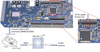
- Connect an MXHS83QE3000 cable to the GPS connector (J6) on the nRF9160 DK.
- Connect the other end of the MXHS83QE3000 cable to the RF connector in the Bias-Tee.
- Connect an external GPS antenna to the RF&DC connector in the Bias-Tee.
- Connect the ground cable from the Bias-Tee to a GND pin in connector P7 on the nRF9160 DK.
- Connect the supply cable from the Bias-Tee to the 5V pin in connector P7 on the nRF9160 DK.
- Connect the nRF9160 DK to the computer or other power source with a micro USB cable