
This blog clarifies what are the basic requirements when nRF9160 is used in signalling/RF testing against R&S CMW290/500 test setups.
Setting up:
The RF attenuations can be modified from RF settings->RF Output/Input->External attenuation from the 'config menu'
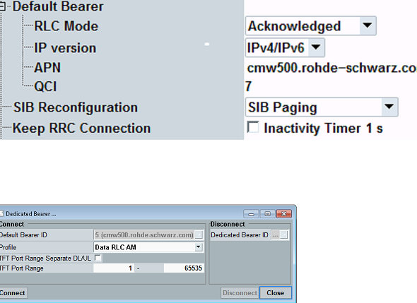
When setting cell and configuration parameters (from GUI config button), note that all RLC modes have to be RLC AM against.
If Default Bearer RLC mode is not present (see screenshot #1), then SW option KS510 is required.
If you are connecting to the internet (and have DAU HW and SW) so not using test mode as connection type then Testmode Dedicated Bearer is disabled (see screenshot #2).
Select to be used band which is supported by nRF9160 and scheduling type as "eMTC auto mode" in the GUI main screen.
'eMTC automode' scheduling type doesn't work as such for RF measurements as subframes and slots need to be configured.
->Use default "RMC" for scheduling type in the GUI main screen for RF measurements.
Enable always "Half Duplex" functionality if selectable (depends on the scheduling type configuration).
When using different SIM cards the usual secret keys in GUI security settings are 000102030405060708090A0B0C0D0E0F (R&S default CMW-Z06 for MCC 001, MNC 01)
or possibly 00112233445566778899AABBCCDDEEFF.
If "authentication failure" is seen in the GUI during attach procedure, then likely incorrect security key is selected.
Use always "Snow3G (EIA1)" as an integrity algorithm and as a NAS Ciphering Algorithm.
Use Nordic proprietary AT commands for selecting M1 or NB IoT mode, (AT%XSYSTEMMODE=1,0,0,0 for Cat M1 and AT%XSYSTEMMODE=0,1,0,0 for NB IoT,
you need to send AT+CFUN=4 for the detach procedure first).
The full list of AT commands supported by nRF91xx can be found from https://infocenter.nordicsemi.com/index.jsp?topic=%2Fref_at_commands%2FREF%2Fat_commands%2Fintro.html
If attach fails with "signaling failure" in the GUI it is likely because of RLC UNack mode being selected (R&S default setting). This is seen
after "RRC connection establishment" in the GUI screen.
To enable UE to go to RRC idle mode, unselect "Keep RRC connection" from GUI "Connection->Default bearer" selection.
Taking logs:
If there is any debugging required, UE or/and tester log would help.
To take tester logs (might not be official way):
- Shut down callbox SW by pressing ALT+F4 and wait that all CMW related windows are closed.
- Start callbox software again with supported/required components (signalling, measurements).
- Re-produce the issue
- Copy whole directory from D-Drive : /Rohde&Schwarz/CMW/Log/"used BaseSW,usually latest"/"Latest directory,timestamped".
In the GUI config there is also a selection to save the log dump to above directories.
Use merge_logs.bat from subdirectories for viewing signalling tester logs with CMWMars.
For NB IoT, above information is almost completely the same although there is no RLC mode / Half duplex / Scheduling type selection issues.
Options required for CMW290/500 M1 testing:
Required CMW290/500 SW options for Cat M1 TX/RX measurements : KM500 (required for TX/RX measurements), KS500, KS510 and KS590.
There is a bundle for above SW options (PK50), at least in some cases it might be feasible to purchase despite it contains functionality also for legacy features (MIMO,TDD etc.)
because of it’s bundle price.
If more than 1 cell is required then HW capability must include more than one TRX(B570H) and possibly more RF advanced HWs(B590D) and SignallingUnitAdvanceds(B500I)
From SW point of view, another KS500 is required per one-cell.
Options required for CMW290/500 NB IoT testing:
Required CMW290/500 SW options for NB IoT TX/RX measurements: KM300 (required for TX/RX measurements) and KS300 .
If more than 1 cell is required then HW capability must include more than one TRX(B570H) and possibly more RF advanced HWs(B590D) and SignallingUnitAdvanceds(B500I).
From SW point of view, another KS300 is required per one-cell.
Note that CMW290 can only have 1 M1 or NB IoT cell active at a time.
Common options :
To enable internet connection, select Data Application in GUI config of Connection type. This testing requires HW option B450I (DAU unit) and SW options like KA100/KA150 and KM050/KM051/KM052 might be required
depending on the testing need.
This can also be bought as a bundle (PK45).
Recallable CMW500 configuration files:
Basic dfl files for M1 and NB IoT signalling are attached below
(uses Band4 and RF1Com, configured to 1 cell testing
External attenuation set to 0dB (depends on CMW500 DUT setup).
No repetitions are configured.
Testmode is configured, no data transfer to internet in this configuration (connection type from Testmode to Data Application change required)
RRC connection is kept to allow data transfer.
These dfl fils are for signalling testing, not for data throughput testing which requires different configuration type.)
Other saved recallable configuration files for M1 and NB IoT are available on request (however there might be some issues if callbox SW versions are different).
Added own cell RSRP/RSRQ measurement support DFL file for CMW500 (Cat-M1).
-

JustinLee
-
Cancel
-
Vote Up
0
Vote Down
-
-
More
-
Cancel
-

MikeS
in reply to JustinLee
-
Cancel
-
Vote Up
0
Vote Down
-
-
More
-
Cancel
-

MikeS
in reply to MikeS
-
Cancel
-
Vote Up
0
Vote Down
-
-
More
-
Cancel
-

JustinLee
in reply to MikeS
-
Cancel
-
Vote Up
0
Vote Down
-
-
More
-
Cancel
Comment-

JustinLee
in reply to MikeS
-
Cancel
-
Vote Up
0
Vote Down
-
-
More
-
Cancel
Children