

Objectives
- Learn to add and configure an I2C/TWI Master Zephyr driver to an NRF Connect SDK project.
- Learn to add and configure an I2C/TWI Slave nRFX driver to an NRF Connect SDK project.
- Demonstrate the I2C/TWI Master and I2C/TWI Slave communication between two nRF52840DKs.
The initial objective of this blog is to understand how to use and configure both the Zephyr I2C/TWI Master and Slave drivers. However, no Zephyr I2C/TWIS Slave Driver supports Nordic I2C/TWI Slave hardware to date. As a result, the TWIM software will use the Zephyr i2c driver, and the TWIS software will use the nRFX driver (NRFX_DRV) paradigm. So, this tutorial also provides insight into integrating a Nordic nRFX driver into NRF Connect SDK.
It is assumed the reader has already installed nRF Connect SDK, the required Toolchain, and is familiar with the process of adding a peripheral to an application. If the reader is unfamiliar with this process, it is recommended to first review Adding a Peripheral to an NCS Zephyr project. The sample code for the Master and Slave will use TWIM1 and TWIS0, respectively. Using the technique provided in Adding a Peripheral to an NCS Zephyr project to merge the Master and Slave examples, one could implement the functionality of this tutorial on a single DK.
The tutorial portion of this document is based on NRF Connect SDK version 1.6.1 and requires the use of two nRF52840-DKs.
The tutorial will demonstrate how to add support for a TWI Master (TWIM) and TWI Slave (TWIS). The initial application for both TWIM and TWIS applications is <install directory> \zephyr\samples\basic\blinky.
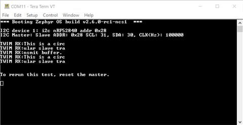
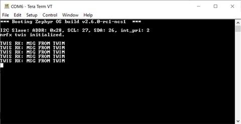
The provided code is configured to write a fixed message “MSG FROM TWIM” to the TWIS. But by setting TWI_LOOPBACK to true the TWIM will first write the message “Begin Loopback.” Each subsequent message written by the TWIM will echo the previously received message fragment read from the TWIS. The complete TWIS message is “This is a circular TWIS transmit buffer.”
If any information in this document contradicts the referenced documentation, the reference documentation is assumed to be more accurate.
I2C or TWI?
Though technically different constructs, TWI and I2C are often considered to be operationally synonymous. Nordic has adopted the TWI nomenclature, while Zephyr has adopted I2C. For this document, I2C will only be used to be consistent with referenced Zephyr software and documentation.
TWIM setup using Zephyr driver
- Build the blinky sample for the nRF52840DK to ensure all the build tools are installed and working correctly and you have a good starting point.
- Copy all the contents of blinky to a new directory named blinky-twim
- Create a text file nrf52840dk_nrf52840.overlay and save it to the directory blinky-twim/boards. This directory may need to be created.
- Add the following node properties to blinky-twim/boards/nrf52840dk_nrf52840.overlay.
/* Overlay for TWI/IC2 Zephyr NCS implementation with nRFx TWIM Driver */
/* Line references are used in the blog post and twim_node.txt */

&i2c1 {										/* a */
	compatible = "nordic,nrf-twim";			/* b */
	status = "okay";						/* c */
	clock-frequency = <100000>;				/* d */

	twis_device1:nRF52840@28 {				/* e */
		// device compatible				/* f */
		label = "i2c nRF52840 addr 0x28";	/* g */
       	reg = <0x28>;						/* h */
   	};
};
Impact:- This overlay modifies the node with identifier &i2c1.
- The compatible is a node property and is critically important to understand. If you are unfamiliar with this property, please review Devicetree Important properties. The compatible nordic,nrf-twim, states the i2c node describes the Nordic nRF TWIM controller. We are using the Nordic TWIM, because Nordic TWI does not support EasyDMA or I2C clock stretching. It is also worth noting that the nRF52840 product specification indicates the TWI peripheral has been deprecated.
- Enables/allocates the i2c node.
- Sets the i2c clock frequency to 100KHz.
- According to the Devicetree Specification, node names should reflect the function of the device. However, to avoid the implication that this child or sub-node of &i2c1 has a standard Zephyr driver, we will use twis_device1 instead of the functional names i2c or bus. (See section 2.2.2 of the Devicetree Specification for a list of recommended node names.) The Devicetree Specification is very in-depth and covers several use cases. The Devicetree Guide is a reduced scope Devicetree Specification tailored for Zephyr users.
For this label, it's important to understand TWIS is the attached device and not the TWIM peripheral on the IC. - If a driver existed for the targeted slave device, its compatible would be set here. For example, compatible = "adi,adt7420";
- "label" is an arbitrary string. We will use this to describe the slave device that the master is addressing.
- The reg property value is dependent on the compatible property and is also described Devicetree Guide Important properties. For this tutorial, the address is arbitrary. However, when a standard i2c device is used, the address of that device must be used. For example, the default address for the ADI adt7420 is 0x00.
The TWIM project retains the default sda and scl pins configuration set in nrf52840dk_nrf52840.dts
Note: Starting at line 166 of nRF52840dk_nrf52840.dts, the default description for i2c1 node includes the comment, "Cannot be used together with spi1." Though SPIM1 and SPIS1 have also deprecated SPI1, they each share the same Base Address as TWIM1 and TWIS1. Only one of these four peripherals can be enabled at a time.
- Searching the Kconfig reference to see the available config_i2c options, we find a couple of options that should be of interest. CONFIG_I2C and CONFIG_I2C_1_NRF_TWIM. CONFIG_I2C is simply enough. But we find the CONFIG_I2C_NRF_TWIM is not directly assignable and is dependent on I2C_NRFX and I2C. Therefore, we all need to add is the following to <install directory \zephyr\samples\basic\blinky-twim\prj.conf
CONFIG_I2C=y
CONFIG_I2C_NRFX=y
Note: Earlier versions of NRF Connect SDK use the MACRO I2C_1 instead of I2C_NRFX.
Instead of searching the kconfig reference, one will likely find using an Interactive Kconfig interface a better option. - Replace <install directory>\zephyr\samples\basic\blinky-twim\src\main.c with the following code.
/*
 * Copyright (c) 2016 Intel Corporation
 *
 * SPDX-License-Identifier: Apache-2.0
 */

#include <device.h>
#include <devicetree.h>
#include <drivers/gpio.h>
#include <drivers/i2c.h>
#include <sys/printk.h>
#include <zephyr.h>

/* 1000 msec = 1 sec */
#define SLEEP_TIME_MS 1000

/* The devicetree node identifier for the "led0" alias. */
#define LED0_NODE DT_ALIAS(led0)

const struct device *led_dev;

#if DT_NODE_HAS_STATUS(LED0_NODE, okay)
#define LED0 DT_GPIO_LABEL(LED0_NODE, gpios)
#define PIN DT_GPIO_PIN(LED0_NODE, gpios)
#define FLAGS DT_GPIO_FLAGS(LED0_NODE, gpios)
#else
/* A build error here means your board isn't set up to blink an LED. */
#error "Unsupported board: led0 devicetree alias is not defined"
#define LED0 ""
#define PIN 0
#define FLAGS 0
#endif

////////////////////////////////////////////////////////////

// TWI Test Configuration

////////////////////////////////////////////////////////////

#define ECHO_WRITES false
#define MSG_EXCHANGE_CNT 5
#define INFINITE_MSG_EXCHANGE false
#define TWI_LOOPBACK false
// In non-loopback mode, the tx message is unchanged.
// In loopback mode the rx buffer acts as both the tx and rx buffer. The rx buffer is updated with each read.


////////////////////////////////////////////////////////////

// Adding TWI Functionality

////////////////////////////////////////////////////////////


#define TWI_BUFFER_SIZE 14
static unsigned char i2c_tx_buffer[TWI_BUFFER_SIZE] = {'M', 'S','G',' ','F', 'R', 'O', 'M', ' ', 'T', 'W', 'I', 'M', '\0'};
static unsigned char i2c_rx_buffer[TWI_BUFFER_SIZE] = "Begin Loopback";

// TWI Master Setup

#define MY_TWIM DT_NODELABEL(i2c1)
const struct device *nrfx_twis_dev1;

static void twim_init(void) {
  int config_result = false;

  nrfx_twis_dev1 = device_get_binding(DT_LABEL(MY_TWIM));

  if (nrfx_twis_dev1 == NULL) {
    printk("\n\nI2C Slave: Device driver not found.\n");
  } else {
    printk("\nI2C device 1: %s\n", DT_PROP(DT_NODELABEL(twis_device1), label));

    config_result = i2c_configure(nrfx_twis_dev1, I2C_SPEED_SET(I2C_SPEED_FAST) | I2C_MODE_MASTER);

    if (!config_result) {
      printk("I2C Master: Slave ADDR: 0x%x SCL: %d, SDA: %d, CLK(Hz): %u\n\n",
          DT_REG_ADDR(DT_NODELABEL(twis_device1)),
          DT_PROP(MY_TWIM, scl_pin),
          DT_PROP(MY_TWIM, sda_pin),
          DT_PROP(MY_TWIM, clock_frequency));
    } else
      printk("\n\nI2C: Configuration error code: %d\n", config_result);
  }
}

// TWI Master Write

void twi_write_tst(void){
  int rtn_code  = 0;
  uint8_t incr  = 0;
  bool loopback = TWI_LOOPBACK;

  if (nrfx_twis_dev1 != NULL) {
       // printk("\nTWIM TX/writing.");
      if (!loopback) { //write repeated default message
        rtn_code = i2c_write(nrfx_twis_dev1, i2c_tx_buffer, sizeof(i2c_tx_buffer), DT_REG_ADDR(DT_NODELABEL(twis_device1)));
      }else{ //use read buffer as write buffer
        rtn_code = i2c_write(nrfx_twis_dev1, i2c_rx_buffer, sizeof(i2c_rx_buffer), DT_REG_ADDR(DT_NODELABEL(twis_device1)));
      }

      if (ECHO_WRITES && (rtn_code == 0)){
        printk("\nTWIM TX:");
        while (incr < TWI_BUFFER_SIZE)
          printk("%c", i2c_rx_buffer[incr++]);
        printk("\n");
      } //rtn_code == 0

      if (rtn_code){
        printk("twi return code %u\n\n", rtn_code);
      }
  } else // twis_dev1 == NULL
      printk("TWIS device is not initialized correctly.\n");
}

void twi_read_tst(void){
  int rtn_code  = 0;
  uint8_t incr  = 0;

  if (nrfx_twis_dev1 != NULL) {
      // printk("\nTWIM RX/reading -->");
      rtn_code = i2c_read(nrfx_twis_dev1, i2c_rx_buffer, sizeof(i2c_rx_buffer), DT_REG_ADDR(DT_NODELABEL(twis_device1)));

      if (rtn_code == 0) {
        printk("TWIM RX:");
        while (incr < TWI_BUFFER_SIZE) {
          printk("%c", i2c_rx_buffer[incr++]);
        };
      printk("\n");
      }

      if (rtn_code)
        printk("twi return code %u\n\n", rtn_code);

  } else //twim_dev1 == NULL
      printk("TWI is not initialized correctly.\n");
}


void main(void) {
  uint16_t twi_test_cnt = MSG_EXCHANGE_CNT;
  bool led_is_on = true;
  uint32_t ret;

  led_dev = device_get_binding(LED0);
  if (led_dev == NULL) {
    return;
  }

  ret = gpio_pin_configure(led_dev, PIN, GPIO_OUTPUT_ACTIVE | FLAGS);
  if (ret < 0) {
    return;
  }

  twim_init();

  while(1){

    gpio_pin_set(led_dev, PIN, (int)led_is_on);
    led_is_on = !led_is_on;

    if((twi_test_cnt) || (INFINITE_MSG_EXCHANGE)){
        twi_write_tst();
        twi_read_tst();

        if(twi_test_cnt){
          twi_test_cnt--;
        }

        if((!twi_test_cnt) && (!INFINITE_MSG_EXCHANGE)){
              printk("\n\nTo rerun this test, reset the master.\n\n");
        }

    }

    k_msleep(SLEEP_TIME_MS);
  }
}
Highlights of changes made to main.c:- Added the include files drivers/i2c.h and sys/printk.h
- Established twim_dev1 bindings
- Print TWIMs configuration
- Use of the i2c_write function.
- Use of the i2c_read functions.
- Verify that blinky-twim successfully builds and program an nRF52840DK. Confirm that LED1 is blinking.
TWIS setup using nRF driver
- Copy all the contents of the previously tested blinky project to a new directory called <..>\zephyr\samples\basic\blinky-twis
- Create a text file nrf52840dk_nrf52840.overlay and save it to the directory blinky-twis/boards. This directory may need to be created.
- Copy the following node properties to blinky-twis/boards/ nbrf52840dk_nrf52840.overlay.
/* Overlay for TWI/IC2 Zephyr NCS implementation with nRFx TWIS Driver */
/* Line references are used in the blog post and twis_node.txt */

&i2c0 {										/* a */
											/* b */
	status = "disabled";					/* c */
	sda-pin = <26>;							/* d */
	scl-pin = <27>; 						/* e */
	interrupts = < 0x4 0x2 >;   			/* f */

	twis_device1:nRF52804@28 {				/* g */
		label = "i2c nRF52840 addr 0x28";	/* h */
       	reg = <0x28>;						/* i */
   	};

   	twis_device2: nRF52840@0 {				/* j */
   		label = "i2c nRF52840 addr 0x00";	/* k */
       	reg = <0x0>;						/* l */
   	};
};

&spi0 {										/* m */
	status = "disabled";					/* n */
};
Impact:- This overlay modifies the node with identifier &i2c0.
- We would typically use the compatible nordic, nrf-twis However, because the i2c slave API/driver in Zephyr is not compatible with Nordic’s TWIS hardware, using nordic, nrf-twis will result in build errors. Therefore, to access and control the TWI hardware, the nRFx TWIS driver is used.
Note: The compatible is set to nordic,nrf-twi in nrf52840dk_nrf82840.dts. - A Zephyr and nRFx TWIS driver would potentially occupy the same memory space. To prevent this, Zephyr needs to be told not to use this space. This is done by setting "status" to disabled.
Though disabled, we can still use the Devicetree to configure the hardware for this project. Therefore, we will continue to set up &i2c0. See the provided code for implementation. - sda-pin is a node-specific property defined in nordic,nrf-twi. We will use this property to replace the hardcoded definitions in the nRFx TWIS driver.
- scl-pin is a node-specific property defined in nordic,nrf-twi. We will use this property to replace the hardcoded definitions in the nRFx TWIS driver.
- "interrupts" is a Base Property defined in nordic,nrf-twi this line sets the Instantiation ID to 4 and the Priority to 2.
- The nRF52840’s TWI slave can listen for two addresses at the same time. Though only twi_device1 is used in this tutorial. To use both addresses, a separate child node needs to be created for each address.
- "label" is an arbitrary string. This tutorial uses it to describe the slave device and its address. In case, it's convenient to use the same label we used to describe the slave device in the TWIM peripheral node in TWIM setup using Zephry driver above.
- TWIS address1
- The nRF52840’s TWI slave can listen for two addresses at the same time. Though only twi_device1 is used in this tutorial, the twi_device2 child node is provided as a reference.
- "label" is an arbitrary string used to describe the slave device's second address.
- TWIS address2
- This overlay modifies the node with identifier &spi0.
- Because SPI1 and TWI1 share the same space, SPI1 must also be disabled.
- Searching the Kconfig reference to review the available nrfx_twis options, we find the macros CONFIG_NRFX_TWIS and CONFIG_NRFX_TWIS1 of the most interest. The NRFX_TWIS description states NRFX_TWIS is selected by NRFX_TWIS*. Because we want to enable NRX_TWIS1, we need to add the following to <install directory> \zephyr\samples\basic\blinky-twis\prj.conf
CONFIG_NRFX_TWIS1=y
Instead of searching the kconfig reference, one would likely find using an Interactive Kconfig interface a better option. - Replace <install directory>\zephyr\samples\basic\blinky-twis\src\main.c with the following code.
/*
 * Copyright (c) 2016 Intel Corporation
 *
 * SPDX-License-Identifier: Apache-2.0
 */

#include <device.h>
#include <devicetree.h>
#include <drivers/gpio.h>
#include <nrfx_twis.h>
#include <zephyr.h>

/* 1000 msec = 1 sec */
#define SLEEP_TIME_MS 1000

/* The devicetree node identifier for the "led0" alias. */
#define LED0_NODE DT_ALIAS(led0)

#if DT_NODE_HAS_STATUS(LED0_NODE, okay)
#define LED0 DT_GPIO_LABEL(LED0_NODE, gpios)
#define PIN DT_GPIO_PIN(LED0_NODE, gpios)
#define FLAGS DT_GPIO_FLAGS(LED0_NODE, gpios)
#else
/* A build error here means your board isn't set up to blink an LED. */
#error "Unsupported board: led0 devicetree alias is not defined"
#define LED0 ""
#define PIN 0
#define FLAGS 0
#endif

#define DEVICETREE_CONF true

#ifndef DEVICETREE_CONF
  //nrfx driver configuration method
  #define SLAVE_ADDR (0x28)
  #define TWI_PIN_SDA 26
  #define TWI_PIN_SCL 27
  #define TWI_INT_PRIORITY 2

#else

//devicetree configuration method
static const uint32_t m_twis_addr0   = DT_REG_ADDR(DT_NODELABEL(twis_device1));
static const uint32_t m_twis_addr1   = DT_REG_ADDR(DT_NODELABEL(twis_device2));
static const uint32_t m_twis_sda_pin = DT_PROP(DT_NODELABEL(i2c0),sda_pin);
static const uint32_t m_twis_scl_pin = DT_PROP(DT_NODELABEL(i2c0),scl_pin);
static const uint8_t  m_twis_prio    = DT_IRQ(DT_NODELABEL(i2c0), priority);

#endif

// be sure TWI_BUFFER_SIZE matches master's tx buffer size.
#define TWI_BUFFER_SIZE 14
static unsigned char twis_rx_buffer[TWI_BUFFER_SIZE];
static unsigned char twis_tx_buffer[] = "This is a circular slave transmit buffer."; //length is whole number multiple of TWI_BUFFER_SIZE
static uint16_t buffer_index;

#define TWIS_INST 1
const nrfx_twis_t m_twis = NRFX_TWIS_INSTANCE(TWIS_INST);

static void twis_event_handler(nrfx_twis_evt_t const *const p_event) {

  uint8_t incr = 0;

  //printk("TWIS EVT handler\n");

  switch (p_event->type) {

  case NRFX_TWIS_EVT_READ_REQ:
    //printk("\nTWIS EVT READ REQ\n");
    if (p_event->data.buf_req) {
          (void) nrfx_twis_tx_prepare(&m_twis,twis_tx_buffer + buffer_index, TWI_BUFFER_SIZE);

          if((buffer_index += TWI_BUFFER_SIZE) >= sizeof(twis_tx_buffer)){
              buffer_index = 0;
          }
    }
    break;

  case NRFX_TWIS_EVT_READ_DONE:
    //printk("\nTWIS EVT READ DONE\n");
    break;

  case NRFX_TWIS_EVT_WRITE_REQ:
    //printk("\nTWIS EVT WRITE REQ 1\n");
    if (p_event->data.buf_req) {
      //printk("\nTWIS EVT WRITE REQ 2\n");
      (void)nrfx_twis_rx_prepare(&m_twis, twis_rx_buffer, sizeof(twis_rx_buffer));
    }
    break;

  case NRFX_TWIS_EVT_WRITE_DONE:
    printk("TWIS RX: ");
    while(incr < TWI_BUFFER_SIZE) {
          printk("%c", twis_rx_buffer[incr++]);
    }
    printk("\n");
    break;

  case NRFX_TWIS_EVT_READ_ERROR:
       printk("\nTWIS READ ERROR\n");
       break;

  case NRFX_TWIS_EVT_WRITE_ERROR:
       printk("\nTWIS WRITE ERROR\n");
       break;

  case NRFX_TWIS_EVT_GENERAL_ERROR:
      printk("\nTWIS GENERAL ERROR\n");
      break;

  default:
      printk("TWIS default\n");
      break;
  } // switch
}

void twis_init(void){

   IRQ_CONNECT(DT_IRQN(DT_NODELABEL(i2c1)),
       DT_IRQ(DT_NODELABEL(i2c1), priority),
       nrfx_isr, nrfx_twis_1_irq_handler, 0);

#ifndef DEVICETREE_CONF
  nrfx_twis_config_t config;

  config.addr[0] = SLAVE_ADDR;
  config.addr[1] = 0;
  config.scl = TWI_PIN_SCL;
  config.scl_pull = NRF_GPIO_PIN_PULLUP;
  config.sda = TWI_PIN_SDA;
  config.sda_pull = NRF_GPIO_PIN_PULLUP;
  config.interrupt_priority = TWI_INT_PRIORITY;

#else

  //devicetree configuration method
  nrfx_twis_config_t dt_config;

  dt_config.addr[0] = m_twis_addr0;
  dt_config.addr[1] = m_twis_addr1;
  dt_config.scl = m_twis_scl_pin;
  dt_config.scl_pull = NRF_GPIO_PIN_PULLUP;
  dt_config.sda = m_twis_sda_pin;
  dt_config.sda_pull = NRF_GPIO_PIN_PULLUP;
  dt_config.interrupt_priority =  m_twis_prio;

#endif

  printk("\nI2C Slave: ADDR: 0x%x, SCL: %d, SDA: %d, int_pri: %d",
      dt_config.addr[0],
      dt_config.scl,
      dt_config.sda,
      dt_config.interrupt_priority);

  if(nrfx_twis_init(&m_twis, &dt_config, twis_event_handler) == NRFX_SUCCESS){
    printk("\nnrfx twis initialized.\n\n");
  }
  else
    printk("\nERROR: nrfx_twis_init()\n");
}


void main(void) {

  const struct  device *dev;
  bool          led_is_on = true;
  uint32_t      ret_code = NRFX_SUCCESS;

  dev = device_get_binding(LED0);
  if (dev == NULL) {
    return;
  }

  ret_code = gpio_pin_configure(dev, PIN, GPIO_OUTPUT_ACTIVE | FLAGS);
  if (ret_code < 0) {
    return;
  }

  twis_init();

  nrfx_twis_enable(&m_twis);

  while (1) {
    gpio_pin_set(dev, PIN, (int)led_is_on);
    led_is_on = !led_is_on;
    k_msleep(SLEEP_TIME_MS);
  }
}
Highlights of changes made to main.c:- The nRFx driver example used to create this example uses some defined macros to set up the hardware. When running a Zephyr project, the better practice is to use the Devicetree for purpose.
The macro DEVICETREE_CONF has been added to switch between nRFx and Devicetree configuration methodologies. - The Zephyr Operating System manages the vector table. Therefore, we need to associate the NRFX IRQ handler with the i2c1’s hardware interrupt vector. We do this by using the IRQCONNECT macro.
IRQ_CONNECT(DT_IRQN(DT_NODELABEL(i2c0)),
            DT_IRQ(DT_NODELABEL(i2c0), priority),
            nrfx_isr, nrfx_twis_0_irq_handler, 0);
nrfx_isr is the entry point of the nRFx twis driver and a wrapper for nrfx_twis_0_irq.
Within the nrfx driver the nrfx_twis_state_machine function callbacks to the applications twis_event_handler.
- The nRFx driver example used to create this example uses some defined macros to set up the hardware. When running a Zephyr project, the better practice is to use the Devicetree for purpose.
- Verify that blinky-twis successfully builds and program a second nRF52840DK. Confirm LED1 is blinking.
Testing
- Power off both nRF52840-DKs.
- Connect the two nRF5284-DKs according to the following Table.
TWIM TWIS GND GND GND P0.31 SCL P0.27 P0.30 SDA P0.26 - Power the two DKs.
- Using your favorite terminal program, connect to the virtual UART (JLINK CDC UART) on each DK. (115200, N, 8, 1)
- Reset the DK running blinky-twis
- Reset the DK running blinky-twim
Output
TIWM
TWIS
Test Options
Throughout both sets of the code, several printk statements have been commented out. You may want to uncomment any of these to assist in fully understanding the flow of the application.
There are a few TWI Test Configuration Options within main-twi.c, which should now be called main.c in the blinky-twim project.
ECHO WRITES: When set to false, each device will only print what it has received. By selecting this macro ECHO WRITES to true, the TWIM will also output the message it has written to the slave device.
MSG_EXCHANGE_CNT: The number of message exchanges to be sent between the TWIM and TWIS.
INFINITE_MSG_EXCHANGE: When set to true, the message exchange is continuous.
TWI_LOOPBACK: When set to true, the first message sent by the master will be “Begin Loopback.” The subsequent messages sent by the TWIS will be returned to the TWIS.
TWI_BUFFER_SIZE must be set to the same value in both main.c files to change the length of the exchange messages.c files.
Additional Resources
The TWIS nRFX code was derived from RF5_SDK_17.0.2\examples\peripheral\twi_master_with_twis_slave (download nRF5 SDK 17.2).
A deep dive into the Zephyr 2.5 device model (I highly recommend viewing this video.)
Source Code
/*
 * Copyright (c) 2016 Intel Corporation
 *
 * SPDX-License-Identifier: Apache-2.0
 */

#include <device.h>
#include <devicetree.h>
#include <drivers/gpio.h>
#include <nrfx_twis.h>
#include <zephyr.h>

/* 1000 msec = 1 sec */
#define SLEEP_TIME_MS 1000

/* The devicetree node identifier for the "led0" alias. */
#define LED0_NODE DT_ALIAS(led0)

#if DT_NODE_HAS_STATUS(LED0_NODE, okay)
#define LED0 DT_GPIO_LABEL(LED0_NODE, gpios)
#define PIN DT_GPIO_PIN(LED0_NODE, gpios)
#define FLAGS DT_GPIO_FLAGS(LED0_NODE, gpios)
#else
/* A build error here means your board isn't set up to blink an LED. */
#error "Unsupported board: led0 devicetree alias is not defined"
#define LED0 ""
#define PIN 0
#define FLAGS 0
#endif

#define DEVICETREE_CONF true

#ifndef DEVICETREE_CONF
  //nrfx driver configuration method
  #define SLAVE_ADDR (0x28)
  #define TWI_PIN_SDA 26
  #define TWI_PIN_SCL 27
  #define TWI_INT_PRIORITY 2

#else

//devicetree configuration method
static const uint32_t m_twis_addr0   = DT_REG_ADDR(DT_NODELABEL(twis_device1));
static const uint32_t m_twis_addr1   = DT_REG_ADDR(DT_NODELABEL(twis_device2));
static const uint32_t m_twis_sda_pin = DT_PROP(DT_NODELABEL(i2c0),sda_pin);
static const uint32_t m_twis_scl_pin = DT_PROP(DT_NODELABEL(i2c0),scl_pin);
static const uint8_t  m_twis_prio    = DT_IRQ(DT_NODELABEL(i2c0), priority);

#endif

// be sure TWI_BUFFER_SIZE matches master's tx buffer size.
#define TWI_BUFFER_SIZE 14
static unsigned char twis_rx_buffer[TWI_BUFFER_SIZE];
static unsigned char twis_tx_buffer[] = "This is a circular slave transmit buffer."; //length is whole number multiple of TWI_BUFFER_SIZE
static uint16_t buffer_index;

#define TWIS_INST 1
const nrfx_twis_t m_twis = NRFX_TWIS_INSTANCE(TWIS_INST);

static void twis_event_handler(nrfx_twis_evt_t const *const p_event) {

  uint8_t incr = 0;

  //printk("TWIS EVT handler\n");

  switch (p_event->type) {

  case NRFX_TWIS_EVT_READ_REQ:
    //printk("\nTWIS EVT READ REQ\n");
    if (p_event->data.buf_req) {
          (void) nrfx_twis_tx_prepare(&m_twis,twis_tx_buffer + buffer_index, TWI_BUFFER_SIZE);

          if((buffer_index += TWI_BUFFER_SIZE) >= sizeof(twis_tx_buffer)){
              buffer_index = 0;
          }
    }
    break;

  case NRFX_TWIS_EVT_READ_DONE:
    //printk("\nTWIS EVT READ DONE\n");
    break;

  case NRFX_TWIS_EVT_WRITE_REQ:
    //printk("\nTWIS EVT WRITE REQ 1\n");
    if (p_event->data.buf_req) {
      //printk("\nTWIS EVT WRITE REQ 2\n");
      (void)nrfx_twis_rx_prepare(&m_twis, twis_rx_buffer, sizeof(twis_rx_buffer));
    }
    break;

  case NRFX_TWIS_EVT_WRITE_DONE:
    printk("TWIS RX: ");
    while(incr < TWI_BUFFER_SIZE) {
          printk("%c", twis_rx_buffer[incr++]);
    }
    printk("\n");
    break;

  case NRFX_TWIS_EVT_READ_ERROR:
       printk("\nTWIS READ ERROR\n");
       break;

  case NRFX_TWIS_EVT_WRITE_ERROR:
       printk("\nTWIS WRITE ERROR\n");
       break;

  case NRFX_TWIS_EVT_GENERAL_ERROR:
      printk("\nTWIS GENERAL ERROR\n");
      break;

  default:
      printk("TWIS default\n");
      break;
  } // switch
}

void twis_init(void){

   IRQ_CONNECT(DT_IRQN(DT_NODELABEL(i2c1)),
       DT_IRQ(DT_NODELABEL(i2c1), priority),
       nrfx_isr, nrfx_twis_1_irq_handler, 0);

#ifndef DEVICETREE_CONF
  nrfx_twis_config_t config;

  config.addr[0] = SLAVE_ADDR;
  config.addr[1] = 0;
  config.scl = TWI_PIN_SCL;
  config.scl_pull = NRF_GPIO_PIN_PULLUP;
  config.sda = TWI_PIN_SDA;
  config.sda_pull = NRF_GPIO_PIN_PULLUP;
  config.interrupt_priority = TWI_INT_PRIORITY;

#else

  //devicetree configuration method
  nrfx_twis_config_t dt_config;

  dt_config.addr[0] = m_twis_addr0;
  dt_config.addr[1] = m_twis_addr1;
  dt_config.scl = m_twis_scl_pin;
  dt_config.scl_pull = NRF_GPIO_PIN_PULLUP;
  dt_config.sda = m_twis_sda_pin;
  dt_config.sda_pull = NRF_GPIO_PIN_PULLUP;
  dt_config.interrupt_priority =  m_twis_prio;

#endif

  printk("\nI2C Slave: ADDR: 0x%x, SCL: %d, SDA: %d, int_pri: %d",
      dt_config.addr[0],
      dt_config.scl,
      dt_config.sda,
      dt_config.interrupt_priority);

  if(nrfx_twis_init(&m_twis, &dt_config, twis_event_handler) == NRFX_SUCCESS){
    printk("\nnrfx twis initialized.\n\n");
  }
  else
    printk("\nERROR: nrfx_twis_init()\n");
}


void main(void) {

  const struct  device *dev;
  bool          led_is_on = true;
  uint32_t      ret_code = NRFX_SUCCESS;

  dev = device_get_binding(LED0);
  if (dev == NULL) {
    return;
  }

  ret_code = gpio_pin_configure(dev, PIN, GPIO_OUTPUT_ACTIVE | FLAGS);
  if (ret_code < 0) {
    return;
  }

  twis_init();

  nrfx_twis_enable(&m_twis);

  while (1) {
    gpio_pin_set(dev, PIN, (int)led_is_on);
    led_is_on = !led_is_on;
    k_msleep(SLEEP_TIME_MS);
  }
}
Top Comments
-

sir_hugo
-
Cancel
-
Vote Up
0
Vote Down
-
-
More
-
Cancel
Comment-

sir_hugo
-
Cancel
-
Vote Up
0
Vote Down
-
-
More
-
Cancel
Children