
Introduction
In a variety of use cases there is a need to share a common clock among multiple devices. Such a common clock can be used for many purposes, for example by having each node in a network perform an action at exactly the same time, or accurately time stamping sensor data.
Wireless protocols such as BLE has a great deal of abstraction from the underlying radio hardware. This is generally a good thing, as the top-level application doesn't have to concern itself with what the underlying protocol might be doing. Calling the send() function ensures that data is sent at some point, regardless of how noisy the RF environment might be. When one wants to synchronize devices with a shared clock, behavior of the underlying protocol is important to understand, especially if the protocol doesn't have built-in mechanisms for timekeeping.
With BLE as an example of a reliable protocol, data packets sent by the top-level application will be re-transmitted by the underlying link layer until the peer acknowledges the packet has been received. The application generally has no idea of how many tries it takes to transmit a packet, which is a problem when it comes to time synchronization. One can correct for this error by sending follow-up packets, but in this blog post a simpler (and more accurate?) approach is looked at: using the SoftDevice timeslot mechanism to transmit and receive accurately timed beacon signals in a proprietary radio mode.
Basic concept
Each node in the network keeps a free-running 16 MHz timer with a 16-bit counter. This means the timer will overflow and wrap around at a rate of about 244 Hz. This timer can be visualized via GPIOTE and PPI, by having a timer compare toggle a GPIO. This is what it looks like when the toggled GPIO is measured with a logic analyzer:  (see list of better resolution images further down)
This free-running timer is the basis for the synchronization. One node in the network will be assigned as the timing master. The goal is to have all other nodes synchronize their free-running timers with the master. By using an oscilloscope or logic analyzer to look at the GPIO output, one can verify how closely in sync the timers actually are.
The timing master will transmit synchronization radio packets at a configurable interval. These packets will contain a value that indicates the time the radio packet was transmitted in relation to the free running 16 MHz timer. When the other nodes receive this packet, they can use this value to update their own timer, by adding a positive or negative offset to the counter value.
Example of timing beacon packet contents:
struct
{
    int32_t timer_val;
    int32_t rtc_val;
} sync_pkt;
Depending on the desired accuracy and power consumption, one can use the RTC instead of timer for lower accuracy and lower power timekeeping. In the code example below, only the 16 MHz timer is used.
Generally, the slower the transmit rate is, the more time the clocks have to drift apart. The trade off is therefor radio activity (power/coexistence) vs accuracy.
Note that both the PPI and Timers run in the 16 MHz clock domain, which means that 62.5 ns (one clock cycle) is to be considered the base timing unit in this design.
Consistency
For accurate timekeeping, it's important to keep all timing-related factors as consistent as possible. This includes:
- Having the timing master send each time beacon packet with the same offset between the timer capture and radio transmission.
- Use the most accurate oscillator for timekeeping (high/low frequency crystal oscillator instead of internal RC)
- Use hardware timers and triggers (not the CPU) for the following:
- Free running timer capture
- Free running timer update
- Packet transmission
- Capture time of packet reception
In particular the last item is important. If the CPU is used for timer manipulation and packet transmission triggering there are a number of other factors that will introduce jitter and offsets: other high-priority interrupts, compiler settings, cache misses (nRF52), memory bus clock domain jitter (nRF52)
Timeslots
The SoftDevice timeslot API allows a top-level application to request access to the radio hardware in between BLE activity. In this example timeslots are used such that normal BLE activity can be run concurrently with the time synchronization functionality.
The code for this example implements the following timeslot behavior:
- By default, each node will request timeslots that will be used to run the radio in RX mode, listening for time beacons. All available radio time will be used for this (not very power effective).
- When Button 1 on the nRF52-DK is pressed, this device will assume the role as the timing master and start transmitting time beacons at a configurable interval (default 100 Hz).
- The code is based on the SDK HTS Example, and the device will be connectable via BLE during the synchronization activity
Test code
The following are snippets from the full code available here: https://github.com/nordic-auko/nRF5-ble-timesync-demo
time_sync.h implements the following API:
typedef struct
{
    uint8_t          rf_chn;          /** RF Channel [0-80] */
    uint8_t          rf_addr[5];      /** 5-byte RF address */
    uint8_t          ppi_chns[3];     /** PPI channels */
    uint8_t          ppi_chhg;        /** PPI Channel Group */
    NRF_TIMER_Type * high_freq_timer[2]; /** 16 MHz timer (e.g. NRF_TIMER2) */
    NRF_RTC_Type   * rtc;
} ts_params_t;

/**@brief SoftDevice system event handler. Must be called when a system event occurs */
void ts_on_sys_evt(uint32_t sys_evt);

/**@brief Initialize time sync library
 *
 * @param[in] p_params Parameters
 *
 * @retval NRF_SUCCESS if successful
 */
uint32_t ts_init(const ts_params_t * p_params);

/**@brief Enable time sync library. This will enable reception of sync packets.
 *
 * @retval NRF_SUCCESS if successful
 */
uint32_t ts_enable(void);

/**@brief Disable time sync library.
 *
 * @retval NRF_SUCCESS if successful
 */
uint32_t ts_disable(void);

/**@brief Start sync packet transmission (become timing master).
 *
 * @note @ref ts_enable() must be called prior to calling this function
 * @note Expect some jitter depending on BLE activity.
 *
 * @param[in] sync_freq_hz Frequency of transmitted sync packets.
 *
 * @retval NRF_SUCCESS if successful
 */
uint32_t ts_tx_start(uint32_t sync_freq_hz);

/**@brief Stop sync packet transmission (become timing slave again).
 *
 * @retval NRF_SUCCESS if successful
 */
uint32_t ts_tx_stop(void);
As indicated by ts_params_t, the code requires the following resources:
- 3 x PPI channel
- 1 x PPI group
- 2 x 16 MHz TIMER
One of the 16 MHz timers is the free running one, the other is used to accurately trigger the master radio transmission. Note that this could be simplified to use only one additional timer, as TIMER0 can be used within timeslots to trigger the radio as well.
The radio parameters used are pretty basic. Note that this code includes use of an nRF52 improvement, the faster radio ramp-up time. Apart from this, the code can be run on the nRF51 as well (expect the same results).
static void update_radio_parameters()
{
    // TX power
    NRF_RADIO->TXPOWER   = RADIO_TXPOWER_TXPOWER_0dBm   << RADIO_TXPOWER_TXPOWER_Pos;

    // RF bitrate
    NRF_RADIO->MODE      = RADIO_MODE_MODE_Ble_1Mbit        << RADIO_MODE_MODE_Pos;

    // Fast startup mode
    NRF_RADIO->MODECNF0 = RADIO_MODECNF0_RU_Fast << RADIO_MODECNF0_RU_Pos;

    // CRC configuration
    NRF_RADIO->CRCCNF    = RADIO_CRCCNF_LEN_Two << RADIO_CRCCNF_LEN_Pos;
    NRF_RADIO->CRCINIT = 0xFFFFUL;      // Initial value
    NRF_RADIO->CRCPOLY = 0x11021UL;     // CRC poly: x^16+x^12^x^5+1

    // Packet format
    NRF_RADIO->PCNF0 = (0 << RADIO_PCNF0_S0LEN_Pos) | (0 << RADIO_PCNF0_LFLEN_Pos) | (0 << RADIO_PCNF0_S1LEN_Pos);
    NRF_RADIO->PCNF1 = (RADIO_PCNF1_WHITEEN_Disabled        << RADIO_PCNF1_WHITEEN_Pos) |
                       (RADIO_PCNF1_ENDIAN_Big              << RADIO_PCNF1_ENDIAN_Pos)  |
                       (4                                   << RADIO_PCNF1_BALEN_Pos)   |
                       (sizeof(m_sync_pkt)                  << RADIO_PCNF1_STATLEN_Pos) |
                       (sizeof(m_sync_pkt)                  << RADIO_PCNF1_MAXLEN_Pos);
    NRF_RADIO->PACKETPTR = (uint32_t)&m_sync_pkt;

    // Radio address config
    NRF_RADIO->PREFIX0 = m_params.rf_addr[0];
    NRF_RADIO->BASE0   = (m_params.rf_addr[1] << 24 | m_params.rf_addr[2] << 16 | m_params.rf_addr[3] << 8 | m_params.rf_addr[4]);

    NRF_RADIO->TXADDRESS   = 0;
    NRF_RADIO->RXADDRESSES = (1 << 0);

    NRF_RADIO->FREQUENCY = m_params.rf_chn;
    NRF_RADIO->TXPOWER   = RADIO_TXPOWER_TXPOWER_Pos4dBm << RADIO_TXPOWER_TXPOWER_Pos;

    NRF_RADIO->EVENTS_END = 0;

    NRF_RADIO->INTENCLR = 0xFFFFFFFF;
    NRF_RADIO->INTENSET = RADIO_INTENSET_END_Msk;

    NVIC_EnableIRQ(RADIO_IRQn);
}
This is the first timing-critical part of the code, which ensures that the timing master captures the free running timer value at a consistent time delta from when the packet is actually transmitted: (snippet from timeslot_begin_handler())
update_radio_parameters();

ppi_chn  = m_params.ppi_chns[0];
ppi_chn2 = m_params.ppi_chns[1];

// Use PPI to create fixed offset between timer capture and packet transmission
// Compare event #0: Capture timer value for free running timer
// Compare event #1: Trigger radio transmission

NRF_PPI->CH[ppi_chn].EEP = (uint32_t) &m_params.high_freq_timer[1]->EVENTS_COMPARE[0];
NRF_PPI->CH[ppi_chn].TEP = (uint32_t) &m_params.high_freq_timer[0]->TASKS_CAPTURE[1];
NRF_PPI->CHENSET         = (1 << ppi_chn);

NRF_PPI->CH[ppi_chn2].EEP = (uint32_t) &m_params.high_freq_timer[1]->EVENTS_COMPARE[1];
NRF_PPI->CH[ppi_chn2].TEP = (uint32_t) &NRF_RADIO->TASKS_START;
NRF_PPI->CHENSET          = (1 << ppi_chn2);

m_params.high_freq_timer[1]->PRESCALER   = 4; // 1 us resolution
m_params.high_freq_timer[1]->MODE        = TIMER_MODE_MODE_Timer << TIMER_MODE_MODE_Pos;
m_params.high_freq_timer[1]->SHORTS      = TIMER_SHORTS_COMPARE1_STOP_Msk | TIMER_SHORTS_COMPARE1_CLEAR_Msk;
m_params.high_freq_timer[1]->TASKS_STOP  = 1;
m_params.high_freq_timer[1]->TASKS_CLEAR = 1;
m_params.high_freq_timer[1]->CC[0]       = 40; // Matches 40 us radio rampup time
m_params.high_freq_timer[1]->CC[1]       = 50; // Margin for timer readout

m_params.high_freq_timer[1]->EVENTS_COMPARE[0] = 0;
m_params.high_freq_timer[1]->EVENTS_COMPARE[1] = 0;

NRF_RADIO->SHORTS                        = RADIO_SHORTS_END_DISABLE_Msk;
NRF_RADIO->TASKS_TXEN                    = 1;
m_params.high_freq_timer[1]->TASKS_START = 1;

while (m_params.high_freq_timer[1]->EVENTS_COMPARE[0] == 0)
{
    // Wait for timer to trigger
    __NOP();
}

m_radio_state                                 = RADIO_STATE_TX;
m_sync_pkt.timer_val                          = m_params.high_freq_timer[0]->CC[1];
m_sync_pkt.rtc_val                            = m_params.rtc->COUNTER;
The second timing-critical part is how the receiver updates its local free running timer when a sync beacon packet is received. Note the magic value "TX_CHAIN_DELAY" in the following code:
static inline void sync_timer_offset_compensate(void)
{
    uint32_t chn0, chn1, chg;
    int32_t peer_timer;
    int32_t local_timer;
    int32_t timer_offset;

    peer_timer  = m_sync_pkt.timer_val;
    peer_timer += TX_CHAIN_DELAY;
    local_timer = m_params.high_freq_timer[0]->CC[1];

    if (local_timer > peer_timer)
    {
        timer_offset = TIMER_MAX_VAL - local_timer + peer_timer;
    }
    else
    {
        timer_offset = peer_timer - local_timer;
    }

    if (timer_offset == 0 ||
        timer_offset == TIMER_MAX_VAL)
    {
        // Already in sync
        return;
    }

    chn0 = m_params.ppi_chns[0];
    chn1 = m_params.ppi_chns[1];
    chg  = m_params.ppi_chhg;

    // Use a timer compare register to reset the timer according to the offset value

    // PPI channel 0: clear timer when offset value is reached
    NRF_PPI->CHENCLR      = (1 << chn0);
    NRF_PPI->CH[chn0].EEP = (uint32_t) &m_params.high_freq_timer[0]->EVENTS_COMPARE[2];
    NRF_PPI->CH[chn0].TEP = (uint32_t) &m_params.high_freq_timer[0]->TASKS_CLEAR;

    // PPI channel 1: disable PPI channel 0 such that the timer is only reset once.
    NRF_PPI->CHENCLR      = (1 << chn1);
    NRF_PPI->CH[chn1].EEP = (uint32_t) &m_params.high_freq_timer[0]->EVENTS_COMPARE[2];
    NRF_PPI->CH[chn1].TEP = (uint32_t) &NRF_PPI->TASKS_CHG[chg].DIS;

    // Use PPI group for PPI channel 0 disabling
    NRF_PPI->TASKS_CHG[chg].DIS = 1;
    NRF_PPI->CHG[chg]           = (1 << chn0);

    // Write offset to timer compare register
    m_params.high_freq_timer[0]->CC[2] = (TIMER_MAX_VAL - timer_offset);

    // Enable PPI channels
    NRF_PPI->CHENSET = (1 << chn0) | (1 << chn1);
}
Results
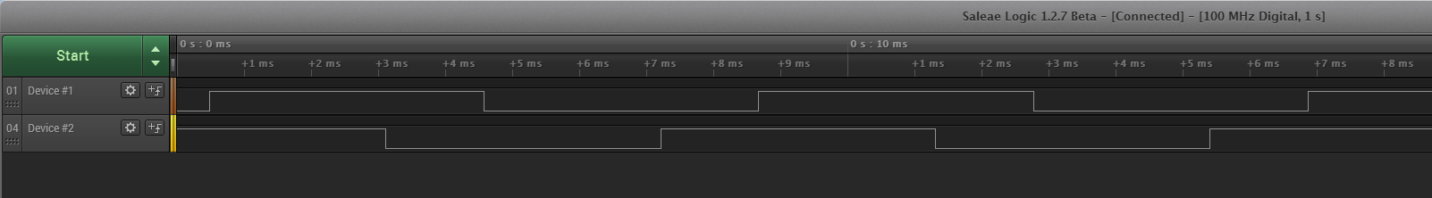
The free running timer is visualized via measuring GPIO toggling on an oscilloscope or logic analyzer. Two nRF52-DKs are used in this test, each of them sitting very close to each other in order to be reached with the Logic Analyzer probes. In a real world scenario the distance will be greater, which will add some jitter (light travels about 19 meters per 16 MHz clock cycle, so expect at least 1 clock cycle of jitter per 19 meters between the devices).
The figure below shows the two devices when no synchronization beacons are transmitted.

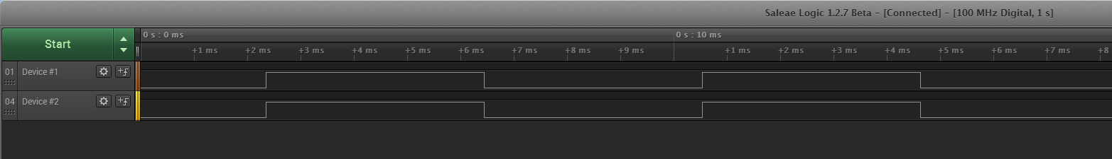
Once one of the devices assumes the timing master role, using a 100 Hz transmit rate, the free running timers line up. Note that the GPIO polarity isn't enforced. The important part is that the GPIOs toggle at the same time.

Closeup of the synchronized signals. In this case the Logic Analyzer reports a 20 nanosecond offset between the two devices.

When analyzing the toggling over time, we can generate some statistics. This is after running the 2-device test setup for 30 minutes:
- 439445 toggles found within sanity range
- Total time in channel 0: 1800.0027646 s
- Total time in channel 1: 1800.00276466 s
- Largest difference: 220.0 ns at toggle #54446 (223.010816 seconds)
- Mean difference across 439445 toggles = 65.6412747898 ns
- Standard deviation across 439445 toggles = 41.0020747807 ns
(Python script that parses Logic16 .vcd files included in git repo)
These results shows that one can stay within one or two 16 MHz clock cycles of synchronization under ideal conditions. Naturally, in the real world there will be packet loss, propagation delay (depending on distance), and reflections that can all degrade timing performance.
Top Comments
-

David Edwin
-
Cancel
-
Vote Up
+1
Vote Down
-
-
More
-
Cancel
Comment-

David Edwin
-
Cancel
-
Vote Up
+1
Vote Down
-
-
More
-
Cancel
Children